EasyManua.ls Logo

Häfele Slido Series User Manual

Häfele Slido Series
16 pages
To Next Page IconTo Next Page
Page #1 background imageLoading...
Page #1 background image
Montageanleitung
Installation instructions
Instructions d’assemblage
Instrucciones de montaje
1/16
HDE 01.03.2012 Maße in mm – Dimensions in mm – Dimensions en mm Medidas en mm
Classic
Festelement
fixed element
élément fixe
elemento de fijación
Slido
gilt für Artikel: siehe Tabelle
applies to Cat. No.: siehe Tabelle
valable pour référence : siehe Tabelle
adecuado para de ref.: siehe Tabelle
940.67.120
940.67.130
940.67.121
940.67.131
H = Gesamthöhe
H = overall height
H = hauteur totale
H = altura total
TH = Türügelhöhe
TH = leaf height
TH = hauteur de vantail de porte
TH = altura de hoja de puerta
FGH = H - 49
20.5 21.5
8
FGH = H - 49
20.5 21.5
8
6(5)
FGH = Festglashöhe
FGH = xed glazing height
FGH = hauteur du vitrage xe
FGH = altura de cristal jo
Question and Answer IconNeed help?

Do you have a question about the Häfele Slido Series and is the answer not in the manual?

Häfele Slido Series Specifications

General IconGeneral
CategoryDoor Opening System
Track MaterialAluminum
TypeSliding
Door Weight Capacity100 kg
MaterialSteel, Aluminum
MountingWall Mount
AdjustmentHeight Adjustment, Side Adjustment (varies by series)
Soft ClosingYes
FinishAnodized or Powder Coated
System TypeSlido Series

Summary

Fixed Element Types

Singled-Side Fixed Element

Details configuration and dimensions for single-sided fixed elements.

Both Sides Fixed Element

Details configuration and dimensions for double-sided fixed elements.

Fixed Element Singled-Side Components

Component Identification

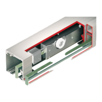
Lists and illustrates necessary parts for singled-side fixed element installation.

Wall Mounting Installation

Step 1: Profile Alignment

First step in wall mounting: aligning and securing the main profile.

Step 2: Drilling and Marking

Marking the wall and drilling holes for mounting hardware.

Step 3: Drilling and Securing Profile

Drilling holes and securing the mounted profile to the wall.

Step 4: Inserting Glass

Steps for inserting glass panels into the installed profile.

Step 5: Attaching Roller Supports

Attaching roller supports to the profile system.

Step 6: Attaching Track Profiles

Securing additional track profiles during wall mounting.

Step 8: Final Wall Profile Assembly

Final step for wall mounting, integrating the last components.

Ceiling Mounting Installation

Step 1: Ceiling Profile Alignment

Initial step for ceiling mounting: aligning the main profile.

Step 2: Drilling and Marking

Marking the ceiling and drilling holes for mounting hardware.

Step 3: Drilling and Securing Profile

Drilling holes and securing the mounted profile to the ceiling.

Step 4: Inserting Glass

Steps for inserting glass panels into the ceiling-mounted profile.

Step 5: Attaching Roller Supports

Attaching roller supports to the ceiling profile system.

Step 6: Attaching Track Profiles

Securing additional track profiles during ceiling mounting.

Step 7: Final Ceiling Profile Assembly

Final step for ceiling mounting, integrating the last components.

Step 8: Securing Rollers

Final step for ceiling mounting: securing the rollers into place.

Fixed Element Both Sides Components

Component Identification

Lists and illustrates necessary parts for double-sided fixed element installation.

Related product manuals