EasyManua.ls Logo

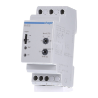
hager EU400 NA-protection User Manual

hager EU400 NA-protection
44 pages
To Next Page IconTo Next Page
Page #1 background imageLoading...
Page #1 background image
K1 K2
12 11 14 22 21 24
EU400
A2A1
24...270 V
~
+
Us
Test
VSR
≤ DC27V/20mA
U> U< f> f<
>>
<<
+Err
I1 Q1 Q2 Q3 Q4 Q5
+
12420-1200-03
Set /
Reset
2 s
L1 L2 L3 N
= tolerance Master-Slave
= regulation
= communication error
= return error K1/K2
= limit error, high < low
= parameter error
= overrange
max 300V
~ L/L max 520V
~ L/N
E1
>2 s
[V,Hz,s,° ]
1
(K1)
= 10 min average
= added time of alarms
= alarm counter
= Scan Modus
Time
~
System-disconnection relay
EU400 NA-protection
Operating Manual
EN

Table of Contents

Questions and Answers:

hager EU400 NA-protection Specifications

General IconGeneral
ModelEU400
Brandhager
Rated current40 A
Protection classIP20
Mounting typeDIN rail
Rated voltage230 V AC

Summary

General Notes on Device Operation

Display and Controls Overview

Control Panel Components

Overview of buttons, LEDs, and display elements on the device.

User Interface Navigation and Keys

Keys for navigating menus, adjusting settings, and managing lock status.

Measurement Allocation LEDs

LEDs indicating voltage and frequency measurement status.

Default Settings and Firmware Versions

VDE-AR-N 4105 Default Settings

Default parameter values for VDE-AR-N 4105:2011 and 4105:2018-11 standards.

VDE-AR-N 4110/4120 Default Settings

Default parameter values for VDE-AR-N 4110:2018-11 and 4120:2018-11 standards.

TOR, VSE, Synergrid Default Settings

Default parameter values for TOR, VSE, and Synergrid standards.

Application and Functions

Application Overview

Describes the device's purpose and compliance with standards.

Summary of Key Functions

Lists the key monitoring and protection features of the device.

Connection Diagrams

Single PV Connection Diagrams

Wiring diagrams for single PV installations with varying section switches.

Multiple PV and Generator Wiring

Wiring for multiple PVs, generator operation, and integrated inverter switches.

Specific Application Wiring

Wiring for medium/high voltage and specific inverter integrations.

Important Information and Assembly

Safety and Important Information

Crucial safety warnings, handling, and electrical precautions.

Device Mounting and Assembly

Instructions for installing the device on a 35 mm rail.

Detailed Description of Device

Connection Terminal Descriptions

Details of device connection terminals and their functions.

Functional Characteristics Overview

Explanation of the device's operational features and behaviors.

Commissioning and Operation

Program Setup and Control Charts

Guide to program selection, setup, and parameter navigation charts.

Parameter Descriptions and Modes

Explanation of parameters and operating modes (display, menu, config).

Key Operational Functions

Covers switching, disengaging, zero voltage, testing, alarms, standby, and locks.

Simulation and Display Indications

How to simulate values and interpret display messages.

Technical Data

Troubleshooting and Measures

Error Code Troubleshooting Guide

Identifies errors and provides remedies for common issues.

Adjustment Values and Settings

VDE-AR-N and BDEW Adjustment Values

Default and adjustable values for various low and medium voltage standards.

Specific Standard Adjustment Values

Default and adjustable values for specific medium/high voltage and Swiss standards.

Related product manuals