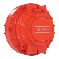
The Hägglunds Compact CB 280 is a hydraulic motor designed for robust and smooth operation, with a strong emphasis on cleanliness during assembly and maintenance to ensure optimal performance.
Function Description
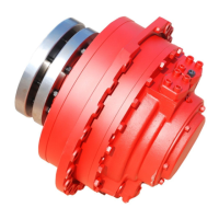
The Compact CB 280 is a hydraulic motor that converts hydraulic energy into mechanical rotational energy. Its design incorporates a cylinder block, pistons, cam rollers, a cam ring, and a valve plate, all working in conjunction to generate torque and rotation. The motor's operation relies on the precise interaction of these components, with hydraulic oil lubricating and transmitting force throughout the system. The motor is designed for applications requiring high cleanliness and careful handling to maintain its smooth functioning.
Important Technical Specifications
- Lifting Capacity Requirement: A lifting capacity of 800 kg (1764 lb) is required for handling during assembly and maintenance.
- Orifice for Flushing: Features a Ø 1 mm orifice in the flushing connection (F1) in the shaft end housing, used specifically for flushing the seal when needed.
- Flushing Connection Plug (F1): G 1/4" plug, requiring an Allen key 6 mm and a torque of 30 Nm (22 lbf·ft).
- Connection Plug (D3): 1" plug in the shaft end housing, requiring an Allen key 12 mm and a torque of 125 Nm (92 lbf·ft).
- Bearing Retainer Screws: Allen key size 10 mm, torque 136 Nm (100 lbf·ft).
- G1" Plug in Bearing Retainer: Allen key 17 mm, torque 125 Nm (92 lbf·ft).
- Puller Tool Bearing Torque: 160-180 Nm (118-133 lbf·ft).
- M20 Hexagon Head Screws (No. 1 to 4): Allen key 17 mm, maximum torque 540 Nm (398 lbf·ft).
- Main Connections Flanges: Allen key 1/2", torque 125 Nm (92 lbf·ft).
- Two Plugs (General): Torque 50 Nm (37 lbf·ft).
- Test Connection T3 (1/4"): Torque 30 Nm (22 lbf·ft).
- Drain Connection Plugs (1 1/4"): Torque 180 Nm (133 lbf·ft).
- End Cover Screws: Spanner size 18 mm, torque 80 Nm (59 lbf·ft).
- M20 Plugs (x4) Covering FRP Holes: Allen key 10 mm, torque 50 Nm (37 lbf·ft).
- Remaining Cover Screws: Spanner size 30 mm, torque 540 Nm (398 lbf·ft).
- Axial Run Out Tolerance: The axial run out between the bearing and the connection block must not exceed 0.03 mm.
- Roller Bearing Heating: Roller bearing should be heated to 110°C (230°F) in an oven for installation.
- Wear Ring Heating: Wear ring should be heated to 110°C (230°F) for installation.
Usage Features
- Cleanliness Criticality: The highest cleanliness of motor parts and the workplace is paramount for the smooth functioning of the hydraulic motor. Contamination must be minimized during assembly.
- Lubrication Requirements:
- Always use clean, filtrated oil, recommended ISO class 16/13 according to ISO 4406, NAS.7.
- Always use clean grease of type Texaco Multifac EP2 or equivalent.
- Oil cleanliness level is important for piston bores, piston balancing surfaces, and axial bearings.
- Rust Protection: Use Shell Ensis SX or equivalent rust protection fluid for surfaces susceptible to rust.
- Gasket Set: Always use a new gasket set for assembly.
- Sliding Surfaces: All sliding surfaces must be treated with care to prevent damage.
- Piston Ring Direction: The direction of the piston ring is important for correct installation.
- Cam Roller Installation: Cam rollers must slide easily into the pistons.
- Piston Assembly: Rollers must be placed on top of the O-ring to avoid damage to the sliding surface during piston assembly into the cylinder block.
- Valve Plate Installation: The valve plate must be installed gently to prevent balancing pistons from falling out.
- Thread Locking: Always install a locating bolt with thread locking, such as middlestrong locking (Loctite No. 243).
- Motor Rotation for Bearing Alignment: The cylinder block should be rotated a couple of turns to align the bearing.
- Seal Direction: The radial lip seal must be turned according to the specified drawing (A4, A62).
- Support for Puller: A support for the puller must be placed on the bearing retainer during bearing tightening.
- Motor Tapping: The motor should be tapped all around (on the rear cover only) after lifting to settle components.
- Roll Pin Installation: Roll pins should be lubricated and installed with the slot in the tangential direction. Superfluous grease must be removed.
- Bearing Race Installation: A plastic mandrel should be used to knock down the bearing race. Cleanliness is very important for this step.
- Axial-Radial Bearing Installation: The axial-radial bearing should be pushed down until the tool is tight against the cylinder block.
- Plugs for Dirt Prevention: Plugs should be placed to prevent dirt from entering the motor.
- Rubber Plugs: Roll pin bores should be sealed with rubber plugs.
Maintenance Features
- Service Inspection Report: It is crucial to note the motor type and individual number from the motor sign in the service inspection report when ordering spare parts.
- Cam Ring Cleaning: It is very important to clean the cam ring thoroughly before assembling.
- Grinding:
- Grind the cam ring surface around the roll pin holes with a fine grinding stone.
- Grind the spacer ring over the roll pin holes with a fine grinding stone on both sides, but do not grind on the sliding surface for the roller.
- Part Cleaning: All motor parts must be cleaned thoroughly, especially if they have been re-machined, ground, or otherwise worked on. Parts should not be left too long after final cleaning before assembling.
- Seal Lip Protection: Care must be taken not to damage the seal lip during installation.
- Bearing Tapping: When tapping down the roller bearing, only tap on the inner race to avoid damage.
- Tool Cleanliness: All tools, especially those used for seals (e.g., D-40063), must be clean and free from damages to avoid destroying the sealing.
- Axial Run Out Adjustment: If the axial run out between the bearing and the connection block exceeds 0.03 mm, the screws must be loosened, and the adjustment process (from A52) repeated.
- Seal Retainer Installation: The seal retainer should be installed after lubricating the radial seal lip and installing the O-ring.
- End Cover Installation: The end cover, screws, and washers should be lubricated before installation.