EasyManua.ls Logo

Haier 1U26JACFRA User Manual

Haier 1U26JACFRA
84 pages
To Next Page IconTo Next Page
Page #1 background imageLoading...
Page #1 background image
SERVICE MANUAL
Wall Mounted Type
DC Inverter
1U26JACFRA
Model No.
This service information is designed for experienced repair technicians only and is not designed for use by the general public.
It does not contain warnings or cautions to advise non-technical individuals of potential dangers in attempting to serviceaproduct.
Products powered by electricity should be serviced or repaired only by experienced professional technicians. Any attempt to service or
Repair the product or products dealt with in this service information by anyone else could result in serious injury or death
WARNING
(Qingdao Haier Air Conditioner General corp.,Ltd)
All rights reserved. Unauthorized copying and distribution is a violation of law
Haier Group
Version V1 Date 2018-06-29
1U35JACFRA
Question and Answer IconNeed help?

Do you have a question about the Haier 1U26JACFRA and is the answer not in the manual?

Haier 1U26JACFRA Specifications

General IconGeneral
BrandHaier
Model1U26JACFRA
CategoryAir Conditioner
LanguageEnglish

Summary

Introduction and Safety

Model Name Explanation

Explains the nomenclature used for model identification.

Safety Cautions and Precautions

Details critical safety warnings for repair, post-repair, and icon usage.

Unit Specifications

1U26JACFRA Specifications

Detailed technical specifications for model 1U26JACFRA.

1U35JACFRA Specifications

Detailed technical specifications for model 1U35JACFRA.

Technical Specifications - Others

Other technical details including refrigerant, piping, and protection degrees.

Sensor Identification and Function

Ambient, Defrosting, and Discharging Sensors

Lists sensors for detecting outdoor conditions and compressor status.

Suction Sensor

Details the suction sensor used for gas flow adjustment.

Refrigerant Piping Diagrams

Cooling Mode Piping Diagram

Illustrates refrigerant flow and component layout in cooling mode.

Heating Mode Piping Diagram

Illustrates refrigerant flow and component layout in heating mode.

Operating Range Charts

Cooling Mode Operation Range

Graph showing indoor/outdoor temperature limits for cooling.

Heating Mode Operation Range

Graph showing indoor/outdoor temperature limits for heating.

PCB Layout and Connectors

Outdoor Control PCB (PCB 1) Connectors

Lists and describes connectors on the outdoor control PCB.

Module PCB (PCB 2) Connectors

Lists and describes connectors on the module PCB.

PCB (1) Connector Wiring Diagram

Visual diagram of PCB (1) connectors and their locations.

PCB (2) Connector Wiring Diagram

Visual diagram of PCB (2) connectors and their locations.

Operational Functions and Controls

Compressor Operation Frequency Control

Details compressor frequency control, speed, and limitations.

Outdoor Fan Control

Explains how the outdoor fan speed is controlled in different modes.

Electronic Expansion Valve Control

Describes the operation and control of the electronic expansion valve.

Protection Functions

Covers various protection mechanisms like temperature and current limits.

Thermistor Value Tables

Provides resistance values for various sensors at different temperatures.

Unit Dimensional Drawings

Outdoor Unit Dimensions

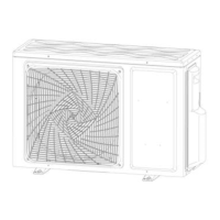
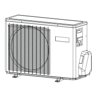
Provides physical dimensions and fixing details for the outdoor unit.

Center of Gravity Information

Outdoor Unit Center of Gravity

Shows the center of gravity for the outdoor unit.

Troubleshooting and Error Codes

Diagnosis Cautions and Problem Symptoms

Initial cautions, common symptoms, and their checks/measures.

Error Code Descriptions

Lists indoor/outdoor error codes and their meanings.

Troubleshooting Flowcharts

Step-by-step guides for diagnosing common faults like EEPROM or fan issues.

Performance Curves and Data

Cooling Capacity-Temperature Curves

Graphs showing cooling capacity vs. temperature for different models.

Cooling Power Consumption Curves

Graphs showing power consumption vs. temperature for different models.

Heating Capacity-Temperature Curves

Graphs showing heating capacity vs. temperature for different models.

Heating Power Consumption Curves

Graphs showing heating power consumption vs. temperature for different models.

Circuit Diagrams

Outdoor Unit Control Board Circuit Diagrams

Detailed circuit diagrams for the outdoor unit control board.

Module Board Circuit Diagram

Circuit diagram for the module control board.

Related product manuals