This document serves as the Operation & Installation Manual for various models of indoor air conditioning units, including AC092MDERA, AC122MDERA, AC162MDERA, AC182MDERA, AC242MDERA, AC282MDERA, AC302MDERA, AC382MDERA, and AC482MDERA. It provides comprehensive instructions for safe operation, installation, and maintenance.
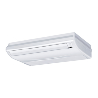
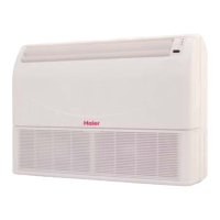
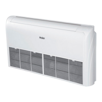
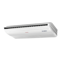
The indoor unit offers considerable operating ease and flexibility, designed to be suspended from the ceiling or stand on the floor. Its ultra-thin design and dazzling exterior allow it to fit well into various indoor scenarios, optimizing space economy. The unit is engineered for superb power and fast temperature tuning, aiming to deliver comfort and pleasure. A key feature is its highly efficient silencing technology, which significantly reduces operating noises, contributing to a more natural and comfortable environment.
For user convenience, the unit includes a Blackout Retrieval function. In the event of a sudden blackout during operation, the indoor unit is capable of retrieving its operating status prior to the blackout once power supply is restored. Integrated Control is available through an integrated controller, enhancing user interaction. For multi-connected unit series, a "uniform control mode" is featured, restricting all indoor units to run on either heating or cooling mode simultaneously. To protect the compressor, the air conditioning unit requires a power-on period of over 12 hours before initial operation.
Safety Considerations
The manual emphasizes critical safety information, divided into "WARNING" and "CAUTION" sections. AWARNING highlights risks that could lead to death or serious injury from improper installation, while ACAUTION addresses issues that could also cause severe accidents. Users are advised to strictly adhere to all safety guidelines.
Key warnings include:
- Always contact a special maintenance station for installation and repair to prevent water leakage, electric shocks, or fire accidents.
- Ensure the air conditioner is installed on a surface capable of bearing its weight to prevent the machine from falling and causing personal injuries.
- The installation must be secured against typhoons and earthquakes to avoid accidents from turnover.
- Use specific cables for reliable wiring connections and fix terminals securely to prevent external force on cables, which could lead to heating or fire.
- Maintain correct wiring shapes, avoiding embossed forms, and ensure reliable connections to prevent the electrical cabinet cover or plate from damaging the wiring.
- When placing or reinstalling the air conditioner, only use the specified refrigerant (R410A) and prevent air from entering the refrigeration cycle system, as abnormal high pressure could cause cracking or injuries.
- Use only accompanied or specific spare parts during installation to avoid water leakage, electric shocks, fire, or refrigerant leakage.
- Do not drain water from the drainpipe into a waterspout where harmful gases (like sulfureted gas) may exist, to prevent them from entering the room.
- In case of refrigerant leakage during installation, ensure adequate ventilation, as refrigerant gas can generate harmful gases when exposed to flame.
- After installation, check for any refrigerant leakage, as leaked gas in the room can generate harmful gases when contacting heat sources like air blowing heaters or stoves.
- Avoid installing the air conditioner in places where flammable gases may leak, as this could cause fire disasters.
- Properly mount the drainpipe with a smooth drainage slope and ensure heat preservation to prevent condensation, which could lead to water leakage and damage to household items.
- Heat insulate the refrigerant gas and liquid pipes to prevent condensation and water dripping.
Key cautions include:
- The air conditioner must be effectively grounded to prevent electric shocks. Grounding wires should not be connected to gas pipes, water pipes, lightning rods, or telephones.
- An electricity leakage breaker must be installed to prevent electric shocks.
- After installation, check for electricity leakage by powering on the unit.
- In ambient humidity greater than 80%, if the water discharge hole is blocked, the filter is dirty, or airflow speed changes, condensation or water drops may occur.
Operational Notices
Several notices guide safe and efficient operation:
- The unit should not be used for preserving food, living creatures, precise instruments, or artworks, as this may cause damage.
- Use fuses with proper capacity to prevent fire or other faults from metal or copper wires.
- Do not use water heaters or similar devices near the indoor unit or wired controller, as steam generation could cause water/power leakage or short circuits.
- Regularly clean the filter to maintain cooling or heating performance, prevent increased power consumption, failure, and water dripping from freezing.
- Do not touch the outlet while the flap is moving or insert anything into the grid to prevent danger.
- During heating, the indoor unit fan will not rotate immediately to prevent cold air from blowing out.
- When refrigerating with automatic blowing, the wind speed decreases as the room temperature approaches the setting. In heating mode, the compressor stops and the fan runs at low speed or stops when the room temperature reaches the setting. Wind speed changes automatically in dehumidifying mode.
- Avoid positioning the wind deflector downwards for extended periods during refrigerating or dehumidifying to prevent condensation and water dripping from the air outlet.
- The machine's operation must always be controlled via the control system.
- During heating, the air conditioner automatically defrosts if frost appears on the outdoor unit's heat exchanger. Do not rotate indoor or outdoor fans during defrosting. After defrosting, the unit resumes automatic running.
- Heating effects are influenced by indoor and outdoor temperatures, as air conditioners absorb heat from the environment and release it into the room.
- Do not place heating apparatus under indoor units, as heat can cause distortion.
- Ensure proper aeration to avoid anoxic symptoms.
- Flammable apparatus should not be placed where the air conditioner's wind can directly reach them, as this may cause incomplete burning.
- Regularly check the air conditioner's mount table for damage to prevent the unit from falling.
- Avoid directing the air conditioner's wind directly at plants and animals to prevent harm.
- Do not touch switches with wet hands to avoid electric shock.
- Switch off the manual power switch when cleaning the unit.
- During control unit operation, do not switch off the manual power switch; the controller can be used. Avoid pressing the liquid crystal zone of the controller to prevent damage.
- Do not clean the unit with water, as this may cause electric shock.
- Do not spray flammable substances near the air conditioner, as this may cause fire.
- When the unit stops operating, the fan will swing for 2-8 minutes every 30-60 minutes to protect the unit while other indoor units are operating.
- This appliance is not intended for use by persons (including children) with reduced physical, sensory, or mental capabilities, or lack of experience and knowledge, unless supervised or instructed by a responsible person.
Maintenance Features
Maintenance is crucial for the longevity and efficiency of the air conditioner.
- Always switch off and disconnect the air cleaner from the power supply before cleaning to prevent electric shock and injury.
Daily Maintenance:
- Cleaning the air outlet port and shell:
- Do not use gasoline, benzene, diluents, polishing powder, or liquid insecticide.
- Avoid hot water above 50°C to prevent fading or distorting.
- Wipe with a soft dry cloth.
- Use water or a neutral dry cleanser for stubborn dust.
- The Wind Deflector can be dismantled for cleaning.
- Cleaning Wind Deflector:
- Do not wipe the wind deflector forcibly with water to avoid it falling off.
- Cleaning Air Cleaner:
- Do not rinse with hot water above 50°C to prevent fading and distorting.
- Do not dry the air cleaner over fire to avoid catching fire.
- Pull the air screen forward to remove it.
- Clean air screens according to their type. Contact after-service staff for details.
- Wipe dust with water or a dust collector.
- For heavy dust, clean with a soft brush and mild detergent.
- Rinse off water and air dry in a cool, dry condition.
Maintenance before and after Operating Season:
- Before Operating Season:
- Perform a checkup: ensure no blockages in inlet/outlet ports of outdoor and indoor units, and verify proper ground line and wiring.
- After cleaning, mount the air cleaner.
- Switch on the power.
- After Operating Season:
- On sunny days, run the blowing operation for half a day to dry the inside of the machine.
- Cut off electrical power to save electricity.
- Mount the air cleaner and shell after cleaning.
Installation Procedures
The manual provides detailed instructions for installing the indoor unit, emphasizing proper placement and connection.
- Site Selection: Choose a location that ensures even circulation of cool and warm air. Avoid coastal areas (high salinity), areas with sulfurized gases (corrosion risk), places with oils/steam, organic solvents, high-frequency electromagnetic waves (control system malfunctions), areas with pervasive humid air near windows/doors (condensation risk), and places where special sprayers are used.
- Indoor Unit Installation:
- Maintain a distance of no more than 2.7m from the air outlet to the floor.
- Ensure outlet airflow covers the entire room area and arrange connecting tubes, wires, and drain pipes to outdoor positions.
- Verify that ceiling structures can bear the unit's weight.
- Connecting tubes, drain pipes, and wires can be routed through walls.
- Keep connecting tubes and drain pipes between indoor and outdoor units as short as possible.
- Refer to the outdoor installation manual for refrigerant charging volume adjustment.
- Users must prepare joint flanges.
- Do not place valuables (TVs, instruments, artworks, pianos, wireless devices) below the indoor unit to prevent damage from condensed water drips.
- Drilling Wall Holes: Drill a 70mm diameter wall hole, slightly tilted downwards towards the outside. Fix a guard ring and seal the hole with gesso or putty.
- Preparation prior to Installing Indoor Unit: Open the intake grill, remove side covers, and refer to "Fresh air intake" for fresh-air intake installation.
- Cutting Intake Grill for Drain Pipe: Use a knife or pliers to cut the intake grill before installing the drain pipe, then pass the drain pipe through the hole as shown in the schematic.
- Floor Type Installation: Instructions for installing the unit on the floor, including drain pipe leading-out direction (high inside, low outside) and distance from obstacles.
- Ceiling Installation: Use M10 hanger bolts (prepared on site) with 60mm hole depth. Ensure balanced installation using leveling instruments. For condensate discharge, side B should be lower than side A.
- Air Conditioner Installation Diagram: Detailed steps for installing hanger chain hooks, mounting racks, and the air conditioner itself. Emphasizes that leveling is forbidden after installation and adjustments should follow the diagram.
- Drain Pipe Leading-out Direction: Drain pipe must be positioned high inside and low outside. Users must prepare drain pipes and ensure connections prevent water leakage. Heat insulation is required for certain indoor drain pipes to prevent condensation.
- Installing Deco Plate and Inlet Grille: This is done after pipeline laying and electric wiring are complete.
Piping Materials & Heat Insulating Materials:
- Heat insulating treatment is essential for water drainpipes and connections to indoor units to prevent condensation.
- Drainpipe design requires a down gradient of 1/100, avoiding S-shapes in elbows to prevent abnormal noise.
- Lateral length of the drainpipe should be within 20m, with supports every 1.5-2m for long pipes.
- Central piping can be connected as shown in the figure.
- Avoid applying external force to drainpipe connections.
- Piping material: Hard PVC tube VP31.5mm (inner bore).
- Heat insulating material: Vesicant polythene, thickness over 7mm.
- Drainage hose: Ø19.05mm (3/4") PVC tube, adjustable for eccentricity and angle. Stretch the hose directly to avoid distortion, secure with a clamp, and use in a horizontal direction.
- Heat insulating treatment: Wrap connections between the clamp and the indoor unit's root segment without gaps.
- Confirming water drainage: During the test run, check for water drainage and leaks, especially in winter.
Refrigerant Tubing:
- Refer to the outdoor unit manual for permissible tubing length and height difference.
- Tubing material: Phosphor deoxybronze seamless pipe (TP2) for air conditioner.
- Refrigerant Filling Amount: Add R410A refrigerant using a measure gauge to ensure the specified amount, as too much or too little can cause compressor failure.
- Connecting Procedures: Use dual wrenches for flare tube connections. Mounting torque specifications are provided for different tubing outer diameters.
- Cutting and Enlarging: Pipes should be cut or enlarged by installation personnel following operating criteria.
- Vacuumizing: Vacuumize from the stop valve of outdoor units with a vacuum pump. Refrigerant sealed in the indoor machine should not be used for vacuumization.
- Open All Valves: Open all valves of outdoor units.
- Checkup for Air Leakage: Check for leakage at connecting parts and bonnets using a hydrophone or soapsuds.
Electrical Wiring
Electrical wiring must be performed by qualified personnel according to installation instructions.
- Safety Warnings:
- Improper power supply capacity can cause electric shock and fire.
- Use specified cables for mains lines, adhering to local regulations. Secure connections to prevent external force on terminals, which could cause burning or fire.
- Ensure proper ground connection to prevent electric shocks. Do not connect grounding lines to gas pipes, water pipes, lightning rods, or telephone lines.
- Cautions:
- Use only copper wire. Install an electric leakage breaker to prevent electric shock.
- Mains line wiring is Y-type: L to live wire, N to null wire, and to ground wire. For units with auxiliary heating, live and null wires must not be misconnected to prevent electrification of the heating body.
- Power lines of indoor units must be arranged according to installation instructions.
- Electrical wiring should avoid contact with high-temperature tubing sections to prevent insulation melting.
- After connecting to the terminal tier, tubing should be curved into a U-type elbow and fastened with a pressing clip.
- Controller wiring and refrigerant tubing can be arranged and fixed together.
- Do not power on the machine before electrical operation. Perform maintenance with power shut down.
- Seal thread holes with heat insulating materials to prevent condensation.
- Signal and power lines are separate and should not share one line. Parameters for power lines: 3×(1.0-1.5) mm²; signal lines: 2×(0.75-1.25)mm² (shielded line).
- 5 butt lines (1.5mm) are equipped in the machine for connection between the valve box and electrical system.
- Supply Wiring Drawing: Diagrams for outdoor units (1, 2, 3) and indoor units (1, 2, 3) show connections for ground fault interruptors and circuit breakers.
- Connection Cables: Indoor and outdoor units must be connected to separate power sources, but indoor units must share a single electrical source. Calculate capacity and specifications.
- Connection Cable Specifications: H05RN-F 4G 2.5mm² for connection cable lengths up to 40m. For 40m < L < 55m, use H07RN-F 4G 4.0mm². For 55m ≤ L ≤ 75m, use H07RN-F 4G 6.0mm².
- Signal Wiring Drawing: Diagrams illustrate communication wiring between indoor and outdoor units, and with wired controllers.
- Line Control and Indoor Units: Three connecting ways:
- One line control for multiple units (2-16 indoor units). SW01 settings differentiate main and sub units.
- One line control for one indoor unit (indoor unit 6-19).
- Two line controls for one indoor unit (indoor unit 20), allowing for master and auxiliary line controls.
- Signal Wiring of Wired Controller: Shielding layer of signal line must be grounded at one end. Total length of signal line not more than 250m.
- Dipswitch Setting (SW01 & SW03): Detailed definitions and descriptions for setting wired control addresses and indoor unit capacity.
Test Run & Fault Code
- Before Test Run:
- Test supply terminal tier (L, N terminals) and grounding points with a 500V megaohm meter; resistance must be above 1MΩ.
- Connect to outdoor unit power supply 12 hours prior to operation to energize the compressor's heating belt and protect it at startup.
- Check Drainpipe and Connection Line Arrangements: Drainpipe should be lower than the connection line. Heat preservation measures are necessary. The drain pipe should be sloped to avoid protrusions and concavities.
- Checkup of Installation: Verify mains voltage, piping joint air leakage, correct power and unit connections, matching terminal serial numbers, installation place suitability, noise levels, fastened connection lines, heat insulated tubing connectors, proper water drainage, and indoor unit positioning.
- Ways of Test Run: Installation personnel should perform a test run to check temperature regulator function. For compulsive running (not available with remote control): set wired controller (E17) to cooling/heating mode, press "ON/OFF" for 10 seconds. Repress "ON/OFF" to quit.
- Fault Remedies: Consult the fault code from the line control or flashing times of LED5 on the indoor unit's computer panel/health lamp on the remote control receiver window to identify and resolve faults. A table lists failure codes and their descriptions (e.g., ambient temp. transducer fault, pipe temp. transducer fault, communication fault, water drainage fault, duplicate address, DC motor fault, BS valve box/4MV reverse fault).
Move and Scrap the Air Conditioning
- For moving, disassembling, or reinstalling the air conditioning, contact your dealer for technical support.
- The composition materials (lead, mercury, hexavalent chromium, polybrominated biphenyls, polybrominated diphenyl ethers) are not more than 0.1% (mass fraction), and cadmium is not more than 0.01% (mass fraction).
- Recycle refrigerant before scrapping, moving, setting, and repairing the air conditioning. Qualified enterprises should handle air conditioning scrapping.