EasyManua.ls Logo

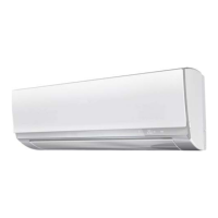
Haier AS18ND1HRA-WHITE User Manual

Haier AS18ND1HRA-WHITE
121 pages
To Next Page IconTo Next Page
Page #1 background imageLoading...
Page #1 background image
SERVICE MANAUL
Wall Mounted Type
DC Inverter FREE MATCH N-Series
AS18ND1HRA-WHITE
HSU18VHGL-G
Model No.
This service information is designed for experienced repair technicians only and is not designed for use by the general public.
It does not contain warnings or cautions to advise non-technical individuals of potential dangers in attempting to service a product.
Products powered by electricity should be serviced or repaired only by experienced professional technicians. Any attempt to service or
Repair the product or products dealt with in this service information by anyone else could result in serious injury or death
WARNING
2014 (Qingdao Haier Air Conditioner General corp. , Ltd)
All rights reserved. Unauthorized copying and distribution is a violation of law
Haier Group
VersionV1 Date2014-05-25

Table of Contents

Questions and Answers:

Haier AS18ND1HRA-WHITE Specifications

General IconGeneral
Cooling Capacity (BTU)18000 BTU
RefrigerantR32
Air Flow (Indoor)850 m³/h
Compressor TypeRotary
Noise Level (Indoor)42 dB
Power Supply220-240V, 50Hz
ColorWhite
TypeSplit
Air Flow850 m³/h
Operating Temperature (Cooling)18-43 °C
Operating Temperature (Heating)24 °C
Dimensions (Outdoor Unit)800
FeaturesAuto Restart, Sleep Mode

Summary

1 Introduction

Model Name Explanation

Explains the model name's components.

Safety Cautions

Details cautions to be observed before conducting repair work.

Caution in Repair

Lists precautions to be taken during repair work.

Cautions Regarding Products after Repair

Lists precautions for products after repair work is completed.

Inspection after Repair

Outlines checks to perform after the repair process is finished.

Using Icons

Explains the purpose and meaning of icons used in the manual.

2. Features

3 Specifications

4. Sensors list

5. Piping diagrams

6. Printed Circuit Board Connector Wiring Diagram

7. Functions and Control

Main Functions and Control Specification

Details the main functions and control specifications of the unit.

Automatic Operation

Explains how the system automatically determines and runs in different modes.

Cooling Operation Mode

Describes the temperature control and airflow settings for cooling mode.

Dehumidifying Mode

Details the operation modes and controls for dehumidifying the room.

Heating Operation Mode

Explains the temperature control and operation for heating mode.

Strength Operation

Describes the function and operation of the strength mode.

Mute Operation

Explains how to activate and use the mute operation mode.

Air Refreshing

Details the air refreshing function and its operation.

Timing

Explains how to set and use the 24-hour timer functions.

Dormant Operation

Describes the dormant operation mode and its temperature adjustments.

Urgent On/Off Input

Explains how to use the urgent on/off function for testing or diagnostics.

Low Load Protection Control

Details the low load protection mechanism for the indoor heat exchanger.

High Load Protection Control

Explains the high load protection for the compressor based on coil temperature.

Abnormal Operation of Indoor System

Describes malfunctions when indoor and outdoor systems operate differently.

Malfunction List Resume

Explains how the malfunction display and resume function work.

Abnormality Confirmation Approaches

Details methods to confirm various abnormalities and sensor failures.

Single Indoor System Operation

Explains how to operate the system with a single indoor unit.

Power Cut Compensation

Describes how the system status is stored upon power interruption.

Fixed Frequency Operation

Explains how to set the unit to fixed frequency cooling or heating.

Test Program

Outlines the procedure for running the test program.

Time Cutting Function

Explains the time cutting function for faster CPU processing.

Value of Thermistor

Provides resistance values for thermistors at different temperatures.

8 System configuration

System Configuration

Details system configuration and operational procedures after installation.

Instruction

Provides instructions for operating and handling the air conditioner.

Parts and Functions

Indoor Unit

Describes the components and functions of the indoor unit.

Remote Control

Details the buttons and functions of the remote control.

Outdoor Unit

Describes the components and functions of the outdoor unit.

Inserting the Battery

Instructions for inserting batteries into the remote control.

Operation

Basic Operation

Explains the basic steps to start and operate the unit.

Emergency Operation and Test Operation

Describes emergency operation and test run procedures.

Air Flow Direction Adjustment

Explains how to adjust the airflow direction manually or automatically.

Sleep Operation

Details the sleep mode for comfortable temperature and noise control.

Power/Quiet Operation

Explains the power operation for rapid cooling/heating and quiet mode.

Timer On/Off Operation

Explains how to set and cancel timer functions for unit operation.

Healthy Airflow Operation

Describes the healthy airflow function and its settings.

Maintenance

For Smart Use of The Air Conditioner

Provides tips for smart usage and operation of the air conditioner.

Replacement of Air Purifying Filter

Step-by-step guide for replacing the air purifying filter.

Cautions

Trouble shooting

Normal Performance Inspection

Checks to perform for normal unit performance.

Noise is Heard

Addresses issues related to unusual noises during operation.

Odors are Present

Explains potential causes for odors from the unit.

Mist or Steam are Blown Out

Discusses reasons for mist or steam being blown from the unit.

Multiple Check

General checks for various operational issues like power or filter.

Installation

Preparation

Lists necessary tools and steps before installing the unit.

Selection of Installation Place

Guidelines for choosing suitable indoor and outdoor installation locations.

Drawing for Installation of Indoor and Outdoor Units

Illustrates the piping and wiring connections during installation.

Fitting of Mounting Plate and Positioning of Wall Hole

Details how to mount the indoor unit's back plate correctly.

Making Wall Hole and Fitting Piping Hole Cover

Instructions for creating wall holes and fitting piping covers.

Installation of the Indoor Unit

Step-by-step guide for installing the indoor unit body.

Fixing the Indoor Unit Body

Explains how to securely fix the indoor unit onto the mounting plate.

Unloading of Indoor Unit Body

Describes the procedure for safely removing the indoor unit from its mounting.

Connecting Indoor/Outdoor Electric Cable

Instructions for connecting the electrical cables between units.

Connection of Pipes

Details the process of connecting the refrigerant pipes.

Cutting and Flaring Work of Piping

Explains the correct methods for cutting and flaring refrigerant pipes.

Purging Method: To Use Vacuum Pump

Describes how to use a vacuum pump for purging the system.

On Drainage

Provides guidelines for proper drain hose installation.

Check Items for Test Run

Lists essential checks before and during the test run.

Dimensional drawings

Center of Gravity

Indicates the center of gravity for the indoor unit.

Service Diagnosis

Caution for Diagnosis

Warns about potential errors and procedures before starting diagnosis.

Parameter of Primary Electronic Appliance

Lists parameters for key electronic components like compressor and fan motor.

Problem Symptoms and Measures

Lists common symptoms and their corresponding checks and measures.

Error Codes and Description Indoor Display

Lists error codes displayed by the unit and their descriptions.

Thermistor or Related Abnormality

Details troubleshooting steps for thermistor sensor failures (E1, E2, etc.).

EEPROM Abnormal

Explains troubleshooting for EEPROM errors (E4, F12).

Indoor Fan Motor Malfunction

Details troubleshooting for indoor fan motor issues (E14).

Outdoor DC Fan Motor Fault

Explains troubleshooting for outdoor DC fan motor faults (LED1 flash 9 times).

IPM Protection

Details troubleshooting for IPM protection faults (LED1 flash 2 times).

Over-current of the Compressor

Explains troubleshooting for compressor over-current faults (LED1 flash 3, 24, 25 times).

Communication Fault Between IPM and Outdoor PCB

Details troubleshooting for communication faults between IPM and outdoor PCB (LED1 flash 4 times).

Power Supply Over or Under Voltage Fault

Explains troubleshooting for power supply voltage issues (LED1 flash 6 times).

Overheat Protection For Discharge Temperature

Details troubleshooting for overheat protection related to discharge temperature (LED1 flash 8 times).

Communication Fault Between Indoor and Outdoor

Explains troubleshooting for communication faults between indoor and outdoor units (E7, LED1 flash 15 times).

Loss of Synchronism Detection

Details troubleshooting for loss of synchronism detection (LED1 flash 18, 19 times).

High Work-Intense Protection

Explains troubleshooting for high work-intense protection (LED1 flash 21 times).

Performance and cerves diagrams

Cooling Capacity-Temperature Curves

Shows cooling capacity variations based on indoor and outdoor temperatures.

Cooling Power Consumption Value-Temperature Curves

Illustrates power consumption based on temperature conditions.

Cooling Discharge Pressure Curves

Displays cooling discharge pressure characteristics across different temperatures.

Cooling Suction Pressure Curves

Shows cooling suction pressure characteristics across different temperatures.

Heating Capacity-Temperature Curves

Presents heating capacity based on indoor and outdoor temperatures.

Heating Power Consumption Value-Temperature Curves

Illustrates heating power consumption based on temperature conditions.

Heating Discharge Pressure Curves

Displays heating discharge pressure characteristics across different temperatures.

Heating Suction Pressure Curves

Shows heating suction pressure characteristics across different temperatures.

Sound level

Circuit diagrams

Outdoor Unit Control Board Circuit Diagrams

Presents the circuit diagram for the outdoor unit control board.

Module Board Circuit Diagram

Shows the circuit diagram for the module board.

Related product manuals