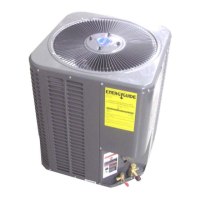
Refrigerant Line Sizing
Refrigerant Line Length (Ft)
0 – 24 25 – 49 50 – 74
Line Outside Diameter (In)
Unit Size
(Ton)
Suction Liquid Suction Liquid Suction Liquid
1.5 3/4 3/8 3/4 3/8 7/8 1/2
2.0 3/4 3/8 3/4 3/8 7/8 1/2
2.5 3/4 3/8 3/4 3/8 7/8 1/2
3.0 3/4 3/8 3/4 3/8 7/8 1/2
3.5 7/8 3/8 11/8 3/8 11/8 1/2
4.0 7/8 3/8 11/8 3/8 11/8 1/2
5.0 7/8 3/8 11/8 3/8 11/8 1/2
The factory charge is sufficient for 25 feet of standard liquid line. For longer or shorter liquid line
lengths, adjust the charge as follows:
1/4" Line +/- 0.3 oz. Per foot
5/16" Line +/- 0.4 oz. Per foot
3/8" Line +/- 0.6 oz. Per foot
1/2" Line +/- 1.2 oz. Per foot.
Vertical Separation between Indoor and Outdoor Units
Maximum allowable vertical separations between indoor and outdoor units are illustrated in Fig.
To ensure good oil return to the compressor when the indoor unit is below the outdoor unit,
17
fittings, as
there is pressure present. A fitting is on the liquid line to remove pressure.
unit liquid and suction valves are closed to contain the charge within the unit. Do not force the valve
stem against the retaining ring. If the valve stem is backed out past the retaining ring, system pressure
could force the valve stem out of the valve body and possibly cause personal injury.
Interconnecting piping
! CAUTION - Use caution when removing the service valves caps from the suction and liquid line
! CAUTION - Condensing units ship from the factory with an operating refrigerant charge. Heat pump
Instructions on the interconnecting piping and valve opening procedure are listed below:
1.Tubing should be cut square. Make sure it is round and free of burrs at the connecting ends. Clean the
tubing to prevent contamination from entering the system.
2.Make sure that both refrigerant shutoff valves at the outdoor unit are closed.
3.Push the tubing into the fitting until it stops. This prevents flux from getting into the system.
4.Remove the cap and Schrader valve core from the service port to protect the valve seals.
5.Wrap a wet rag around the valve stub before brazing.
7.After brazing quench with a wet rag to cool the joint. Reinstall the Schrader core in the valve, if
removed for brazing.
6. Braze the joints of interconnecting piping. purge piping with dry nitrogen through the shutoff valve port
while brazing.
Central Air Conditioning Model: Condensing Unit, HC13-D2
8-2-C and Fig. 8-2-B. It's 70' when the indoor unit is below the outdoor unit (Fig.8-3-B), and 50'
suction line oil trap should be used as illustrated in Fig. 8-2-B.
when the indoor unit is above the outdoor unit (Fig. 8-2-B) .C
Table 8-1

 Loading...