3.2 Outdoor discharging temp. sensor: R80=50K±3%, B25/80=4450K±3%, with copper terminal
3.5 Signal continueous detecting time:
Pressure switch 30seconds
Sensor value 20seconds
Sensor failure (short circuit/open circuit) 2minutes
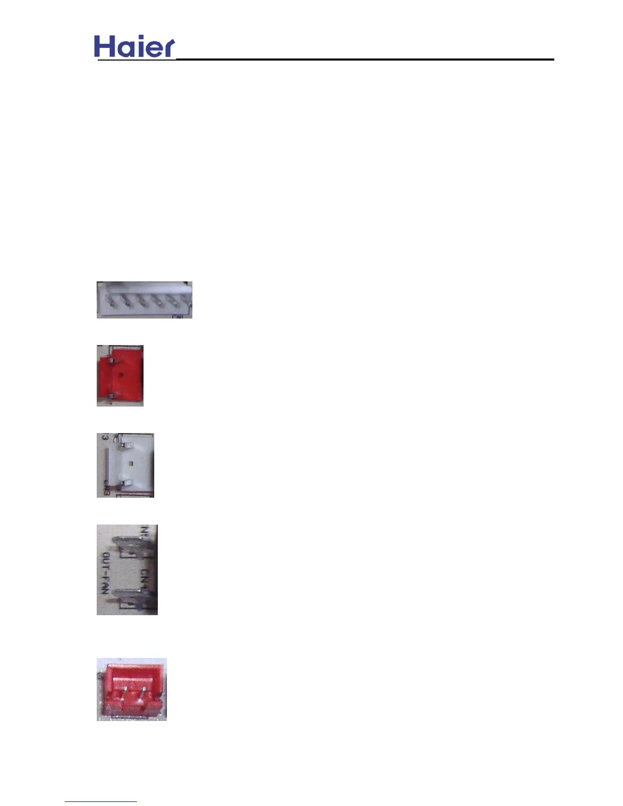
4. PCB port function
4.1 CN1——1,2,3,4 are corresponding to the input signal of R,C,Y,O. R: live line, 24VAC; C: neutral
line, 0VAC; Y: 24V compressor input signal; O: 24V 4-way valve input signal. 5 is electric heating
output signal, and used as 24V signal output to start up the electric heating function when
defrosting. 6: pre-set.
See the figure, from left to right, they are 1,2,3,4,5,6.
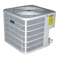
4.2 CN2——24VAC control signal + 0VAC neutral line output; to control AC contactor winding.
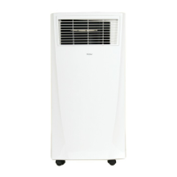
4.3 CN3——24VAC control signal + 0VAC neutral line output; to control 4-way valve winding.
4.4 CN4, CN5——fan motor control port to control the neutral line of outdoor motor.
4.5 CN6——outdoor coil temp. sensor connector; the coil temp. sensor connected /disconnected
failure: 30seconds later alarm; the failure can be resumable.
3.3 High pressure switch: N.C. type pressure switch, the open pressure: 435Psi / close pressure:
3.4 Low pressure switch: N.C. type pressure switch, the open pressure: 7.25Psi / close pressure:
377Psi; (adjustable)
21.75Psi; (adjustable)
36
Central Air Conditioning Model: Heat Pump, HR13-D1