35
10
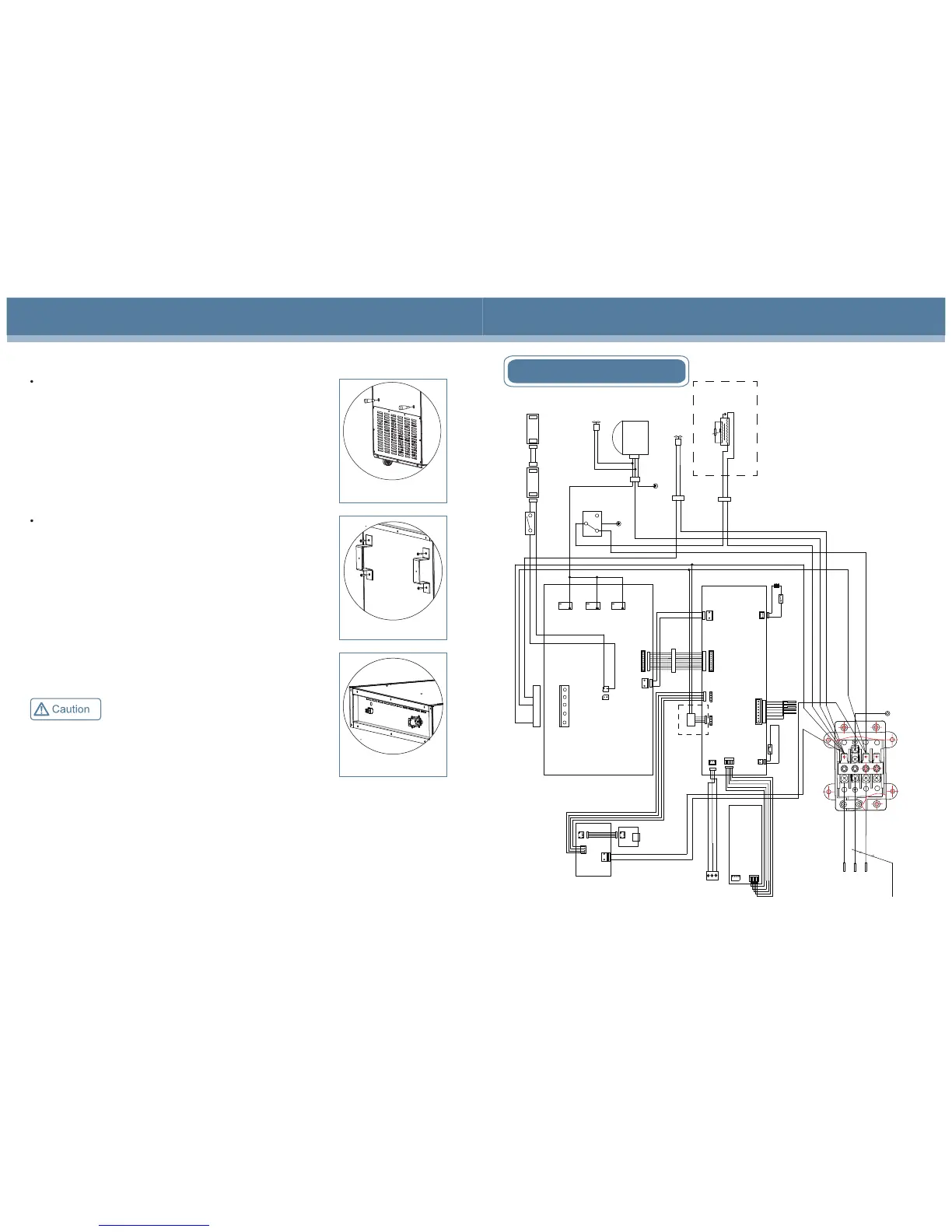
Circuit diagram(HYC-290/390/390F)
CN2
CN2
CN1
CN3
CN11
BT1
BAT+
BAT-
Main control panel
CN5
Display panel
CN2
CN3
Sensor
Alarm
Defrosting
Control
Lower temperature
Upper temperature
VCC
GND
CN1
t
Door heating strip
Door heating transformer
CN1
J5
L N
USB drive plate
CN1
16V
GND
16V
GND
CN7
Battery switch
Lamp switch
C
H
L
Power panel
N
L
FAN
HTR
NC
NC
NC
NO
NO
NO
K3
K7
K4
CN5
CN4
CN2
CN4
USB
PRINT
CN4 and CN5 are both LED
power supply interfaces.
Condensate fan
Internal fan
USB transfer plate
LED lamp bank
Power line
L
N
E
1
L
N
2
L
N
Terminal box of power line
Grounding
CN2
CN1
GND
+12V
Note: Cables at
terminal C and
terminal H of the
mechanical
thermostat can be
exchanged.
CN6
NO
COM
NC
NO
COM
NC
Remote alarm port
Compressor
Note: The content in the frame with dotted lines are
applicable for products with the printer.
LED lamp bank
Printer
door
Door switch
Note: HYC-390F has no Door heating strip,
Door heating transformer and mechanical
thermostat.
8.Back Bracket(HYC-260/360/290/390/390F)
Pic.5
9. Power line bracket installation (HYC-290/390/390F)
Use two M3.5 screws to fix the power line brackets to the refrigerator.
(See Pic.5)
For the power supply cable with loose prevention hook it is not
configured clamp stand.
Remove four M5 bolts from the back of cabinet,then fix the back
bracket for rear wall distance with the removed bolts.(See Pic.4)
Pic.4
HYC-290/390/390F
Pic.3
Install the support bolts into the mounting holes on the back of the
refrigerator. (See Pic.3)
HYC-260/360
 Loading...