Commercial Air Conditioner
1.9.3. Installation drawing
L
N
(1PH, 220V AC power source)
0010451974A
ICR01
Central controller
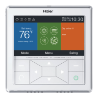
Figure 3. back of central controller
1.9.5. Communication wire specs
The wire between connecting board to the central controller is the dual-core STP (shielded twisted pair).
The detailed specs are as below:
wire length(m)
<
100
100 and
<
200
200 and
<
300
300 and
<
400
400 and
<
600
Specs
0.3mm
2 * 2-core STP
0.5mm
2 * 2-core STP
0.75mm
2 * 2-core STP
1.25mm
2 * 2-core STP
2mm
2 * 2-core STP
Shielded layer of communication wire must be earthed on one end.
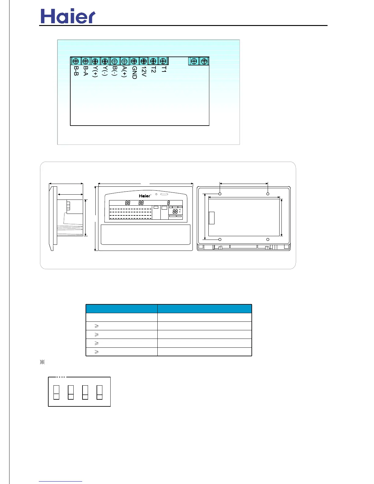
Dip switch setting meaning:
The first bit: central bux line selection, 0: indoor bus line(Install without IGU04); 1: central bus line
The second bit: master/slave central controller selection, 0: master central controller; 1: slave central
controller
The third, fourth bit: control range, 00: 1~64, 01: 65~128, 10: 129~192, 11: 193~256. Every central
controller only can control 64 units, and every unit can include max. 16 indoors, but the central controller
only displays the master indoor state.
O N
1 2 3 4
1.9.6. Dip switch setting of central controller: shown in the below figure (ON:0, OFF: 1)
Figure 4: Exterior dimension
(mm)
65
49
70
180
121
92
136
7086
R
1.9.4. Exterior dimensions for central controller
1
17
33
49
2
18
34
50
3
19
35
51
4
20
36
52
5
21
37
53
6
22
38
54
7
23
39
55
8
24
40
56
9
25
41
57
10
26
42
58
11
27
43
59
12
28
44
60
13
29
45
61
14
30
46
62
15
31
47
63
16
32
48
64
M
O
N
I
T
O
R
S
E
T
MODE
FAN
COOL
DRY
HEAT
AUTO
1
2
G
R
O
U
P
T
O
T
A
L
U
N
I
T
R
U
N
S
T
O
P
C
E
N
T
R
A
L
L
O
C
K
S
L
A
V
E
T
I
M
E
R
S
T
A
N
D
B
Y
F
I
L
T
E
R
FAN
SPEED
AUTO
HIGH
MID
LOW
S
E
T
F
A
I
L
U
R
E
C
H
E
C
K
R
E
C
O
V
E
R
Y
S
W
I
N
G
A
U
T
O
N
O
R
M
A
L
H
R
V
z 36 z
 Loading...