12 Connecting board IGU04 0010451976
IGU04 detector is used with ICR01 central controller, IGU04 appearance and dimension is same with
detector YCJ-A001
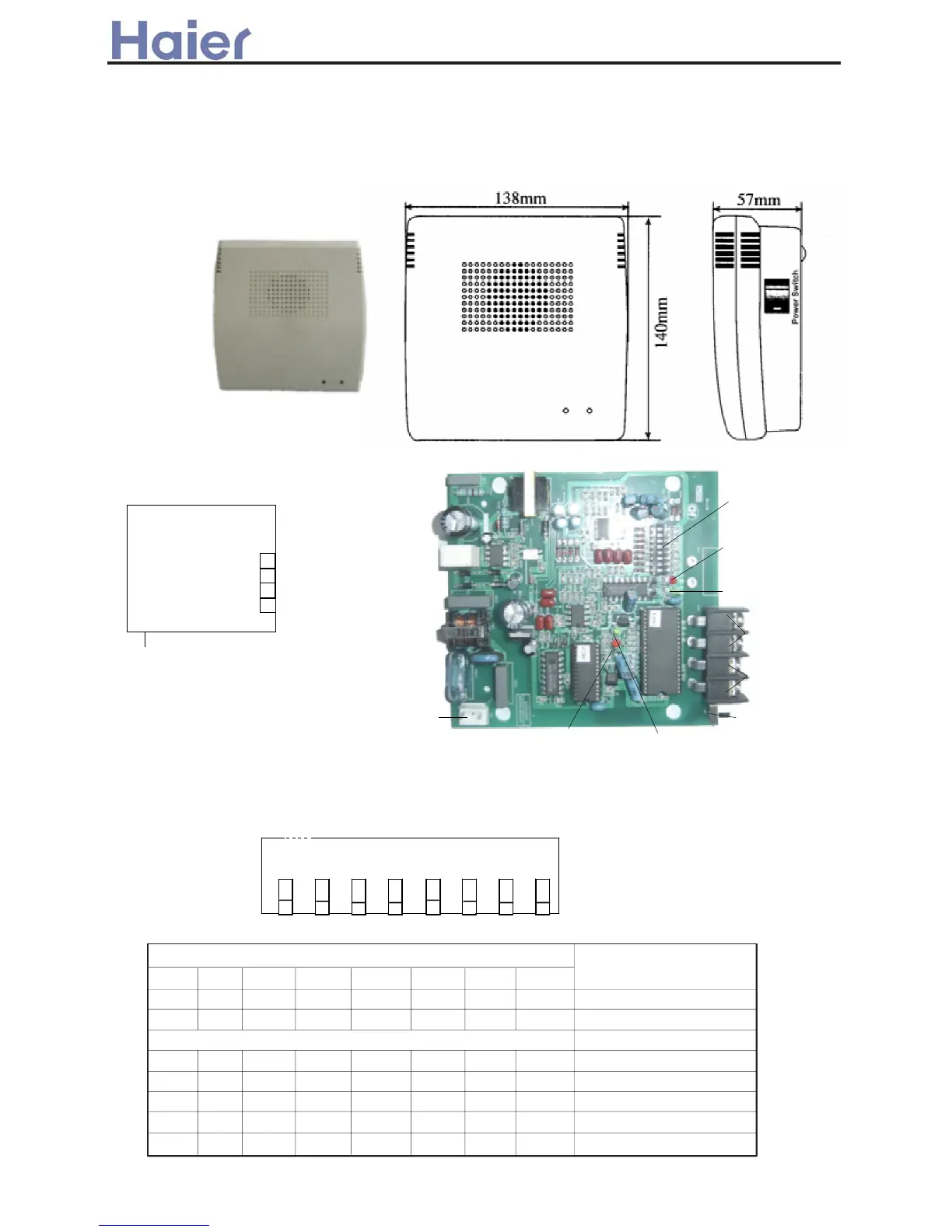
12.1 Appearance
Caution: One central controller can control Up to 5 units of IGU04
CN1
J4
From central
controller
To indoor
units
S1
LED2
LED3
LED1
B-A
Q
P
B-B
From central
controller
To outdoor
units
IGU04
To 220V,50Hz
12.2 PCB photo and drawing
2. Dip switch setting of connecting board ICR01
The dip switch is as below figure (ON:1, OFF: 0):
O N
1 2 3 4 5 6 7 8
S1
LED4
Chff^j\bZe Abj Chg]blbhg^j
z 57 z
=>G<F@EH@DC
8.9 8/9 819 829 839 849 859
J J ------<DCC><H@C? ;D:F= :==F>GG 7.
J J -----.<DCC><H@C? ;D:F= :==F>GG 7/
,,,,
J J -....-<DCC><H@C? ;D:F= :==F>GG 730
J J -.....<DCC><H@C? ;D:F= :==F>GG 731
J-
<>CHF:A ;IG A@C>6 03--;:I=
J. <>CHF:A ;IG A@C>6 /1--;:I=
. B:CI:A G>H :==F>GG
809
EDG@H@DC