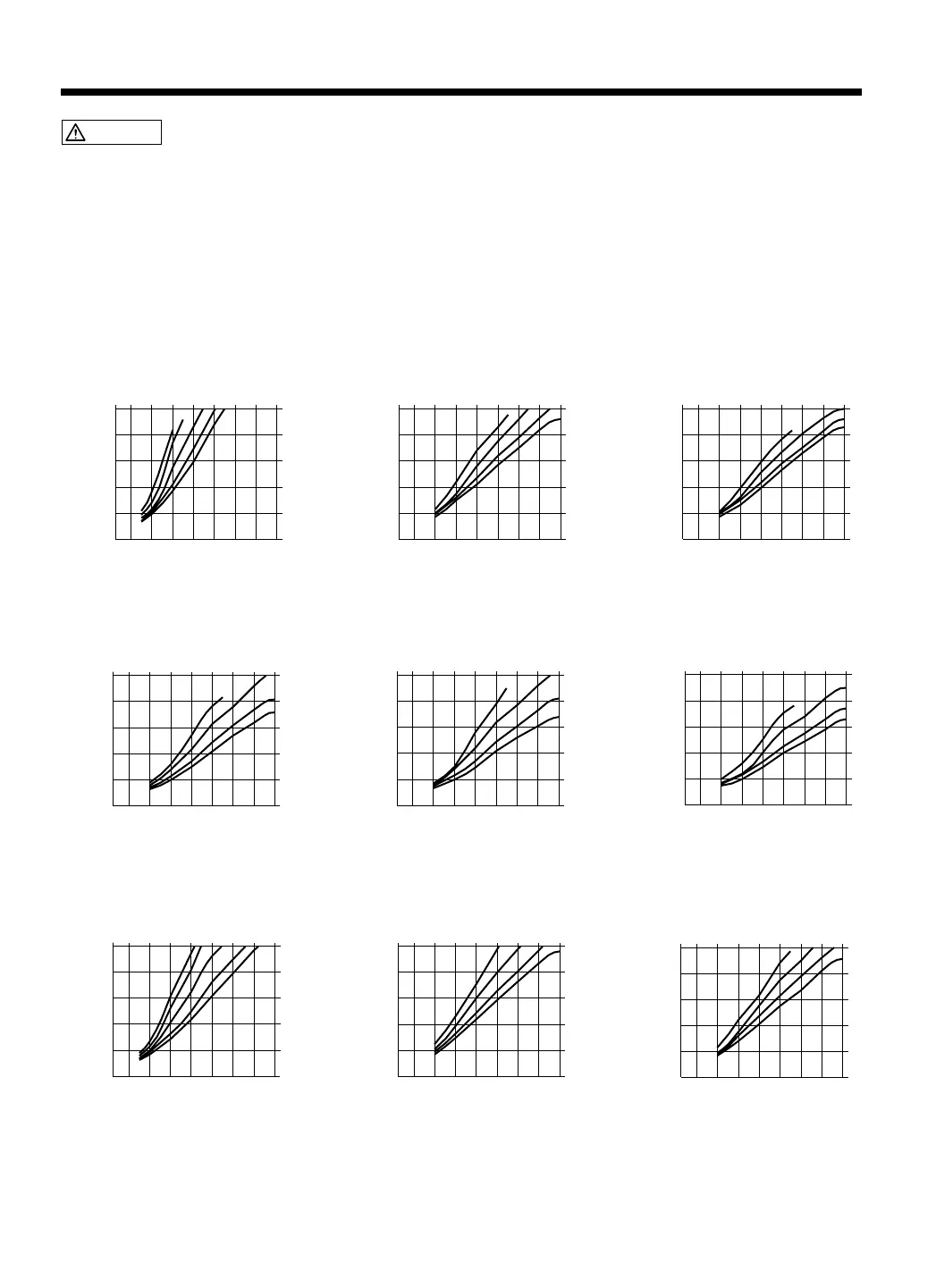
TEMPERATURE DISTRIBUTION CHART
CAUTION These charts are for reference. If the thermal protector trips, reduce the temperature setting
or increase the air flow.
NOTE: Air-flow and temperature adjustment of the Hakko 850B
The temperature distribution chart relating air-flow and temperature settings for different nozzle types
provided with the Hakko 850 are not to be used with the 850B. The 850B uses a different pump and control
system and the flow-rates and temperature do not correspond.
Please refer to the temperature distribution chart in the 850B instruction manual before use.
Test criteria: Measured at a point 3mm (0.12 in.) from the nozzle by recorder.
A1124B
Single Ø2.5 (0.09)
Air flow
Temperature Control Knob
Air Temperature
˚C
1
2
4
68
15842736
Temperature Control Knob
15842736
Temperature Control Knob
15842736
Temperature Control Knob
15842736
Temperature Control Knob
15842736
Temperature Control Knob
15842736
Temperature Control Knob
15842736
500
(932˚F)
300
(572˚F)
100
(212˚F)
Air Temperature
˚C
500
(932˚F)
300
(572˚F)
100
(212˚F)
Air Temperature
˚C
500
(932˚F)
300
(572˚F)
100
(212˚F)
Air Temperature
˚C
500
(932˚F)
300
(572˚F)
100
(212˚F)
Air Temperature
˚C
500
(932˚F)
300
(572˚F)
100
(212˚F)
Air Temperature
˚C
500
(932˚F)
300
(572˚F)
100
(212˚F)
Air Temperature
˚C
500
(932˚F)
300
(572˚F)
100
(212˚F)
Air Temperature
˚C
500
(932˚F)
300
(572˚F)
100
(212˚F)
Air Temperature
˚C
500
(932˚F)
300
(572˚F)
100
(212˚F)
Air flow
2
46
8
A1125B
QFP 10×10 (0.39×0.39)
Air flow
2
4
6
8
A1126B
QFP 14×14 (0.55×0.55)
Air flow
2
4
6
8
A1129B
QFP 28×28 (1.1×1.1)
Air flow
2
4
6
8
A1128B
QFP 14×20 (0.55×0.78)
Air flow
2
4
6
8
A1127B
QFP 17.5×17.5 (0.68×0.68)
Air flow
2
4
6
8
1
A1130
Single Ø4.4 (0.17)
Temperature Control Knob
15842736
Temperature Control Knob
15842736
Air flow
2
4
6
8
A1131
SOP 4.4×10 (0.17×0.39)
Air flow
2
46
8
A1132
SOP 5.6×13 (0.22×0.51)
8


 To Next Page