Do you have a question about the Hallicrafters FPM-300 and is the answer not in the manual?
Hallicrafters Model FPM-300 is a precision-built, high performance transceiver of advanced design.
The FPM-300 Transceiver has been designed and constructed to suppress spurious radiation that may cause television interference.
The following items are available to complement the FPM-300 Transceiver in various installations and operating modes.
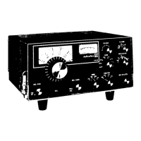
All controls utilized during normal operation of the FPM-300 Transceiver are located on the front panel.
The tuning control knob is located just below the dial display. The control drives the VFO capacitor.
This is a combination RF sensitivity control and power on-off switch.
The CAL. control varies the frequency of the VFO over a narrow range of frequency.
This combination volume control and switch serves two functions.
The MODE control is a four-position switch used to select the mode of transmission or reception.
The FUNCTION control is a four-position switch used to select the transceiver function desired.
Adjusts the transmitter audio level to the modulator stage.
An eight-position rotary switch used to select the desired operating frequency range.
Tunes both receiver and transmitter circuits to a frequency within a given band.
Drives a variable capacitor that tunes the pi-network used to couple the PA stage to the antenna load.
Drives a variable capacitor that provides a small load adjustment for the final amplifier stage.
The operating procedure for the FPM-300 Transceiver is not complicated; however, normal care should be exercised.
The transmitter group of controls, not specifically mentioned below, have no direct bearing on receiver operation.
Procedure for calibrating the transceiver's dial for accurate frequency readings.
Procedure for tuning the transceiver for optimal transmitter performance.
Instructions for safely removing the top, bottom, and chassis covers of the transceiver.
Procedure for replacing the dial and meter lamps in the transceiver.
Steps for accessing and replacing the final amplifier tube.
Steps for accessing and replacing the driver amplifier tube.
Guidance on diagnosing and correcting malfunctions in the transceiver.
Information on obtaining further assistance for operation or servicing.
Guidance on transceiver alignment and the need for experienced service personnel.
List of specialized test equipment needed for proper transceiver alignment.
Procedure for setting the final amplifier bias for correct idle plate current.
Procedure for adjusting carrier balance controls for minimum residual transmitter carrier output.
Procedure for adjusting the 100 kHz crystal calibrator for exact frequency.
Checks and procedures for neutralizing the final amplifier stage for stable operation.
Steps for aligning the VFO capacitor and coil for accurate dial calibration.
Procedure for adjusting transformers for maximum injection level to the signal mixer.
Procedure for adjusting coils and transformer for maximum RF output.
Aligning mixer, amplifier, and driver stages using internal signals for optimal output.
Adjusting carrier oscillator transformer and crystal trimmers for exact frequency.
| Brand | Hallicrafters |
|---|---|
| Model | FPM-300 |
| Category | Transceiver |
| Language | English |