
W
William GutierrezJul 31, 2025
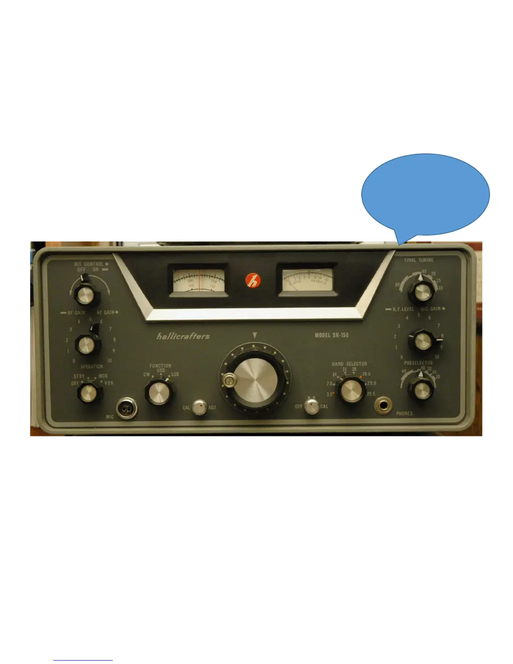
What to do if there is no sufficient injection from pin 7 V6 in Hallicrafters SR-150 Transceiver?
- KKelly HardyJul 31, 2025
If the Hallicrafters Transceiver shows insufficient injection from pin 7 V6, verify pin 7 V6 for 25vpp of injection from carrier oscillator, and inspect V6 along with its related circuitry.