Do you have a question about the Hallicrafters HT-40 and is the answer not in the manual?
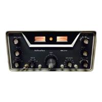
Describes the Hallicrafters Model HT-40 transmitter, its capabilities, and basic requirements for immediate operation.
Details design elements and filtering to suppress spurious radiations and prevent television interference (TVI).
Covers emission types, frequency coverage, power input, output impedance, and component details like tubes.
Details power source requirements, physical dimensions, net and shipping weight of the transmitter.
Instructions for unpacking the HT-40 transmitter and carefully checking for any possible damage incurred during transit.
Guidance on selecting a suitable location for the unit, considering air circulation, and connecting the correct AC power source.
Details on connecting external VFO, key, microphone, and antennas, including accessory terminal strip functions.
Explains the five-position rotary switch used to select the transmitter's mode of operation: OFF, TUNE, STANDBY, AM, or CW.
A six-position rotary switch used to select the proper inductance in the driver and final amplifier pi network for each band.
A variable capacitor used to tune the plate circuit of the buffer stage and the input tuning capacitor.
A slide switch that permits the HT-40 to operate either crystal controlled or from an external VFO.
A switch that allows the operator to switch the meter either into the grid circuit or across the RF output load.
A variable capacitor in the output pi network section that adjusts the plate load impedance.
A variable capacitor that tunes the plate circuit of the final amplifier (6DQ5) to the desired operating frequency.
A potentiometer controlling the audio signal applied to the grid of the audio amplifier tube.
General advice on transmitter tuning, emphasizing the importance of good operating technique for a clean signal.
Detailed step-by-step procedure for tuning the transmitter for CW (Continuous Wave) operation, including equipment required.
Procedure for tuning the transmitter for AM (Amplitude Modulation) operation, identical to CW except for microphone connection.
Explains the crystal oscillator circuit (V1) and the buffer-multiplier stage (V1) operation.
Details the final amplifier stage utilizing a 6DQ5 beam pentode, operating as a straight-through amplifier or frequency doubler.
Describes the RF output-grid current meter's functions and the speech amplifier/modulator stages for AM transmission.
Explains the power supply circuit, voltage doubler, and the LC filter to prevent conducted television interference.
Instructions for removing the chassis from the cabinet to access tubes and pilot light for replacement.
Guidance on troubleshooting common malfunctions, emphasizing tube substitution and referencing the service parts list.
| Brand | Hallicrafters |
|---|---|
| Model | HT-40 |
| Category | Transmitter |
| Language | English |