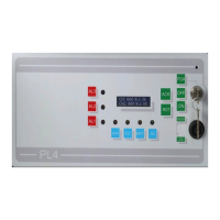
Assieme centrale
1-Alimentatore
2-Batteria 12V 7Ah
3-Scheda elettronica
4-Morsetti rilevatori (1-4)
5-Relè e morsetti
6-Chiave elettronica
Part identification
1-Power supply
2-Battery 12V 7 Ah
3-Main electronic board
4-Detector (1-4) terminals
5-Relays and terminals
6-Electronic key
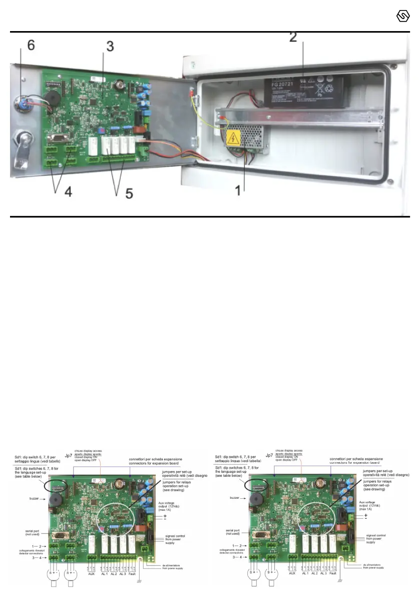
Layout scheda principale
La figura rappresenta la scheda montata sul retro dello
sportello frontale, su cui dovranno essere eettuati i cablaggi
dei rivelatori.
Main board layout
The above figure shows the PCB mounted on the rear side of
the front door, to which gas detectors are to be connected.
SENSITRON
A Halma Company
MT4359
PL4+
Quick Guide
P. 3/4