Do you have a question about the Hameg HM8011-3 and is the answer not in the manual?
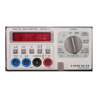
Details the function and use of each pushbutton, socket, and display on the multimeter's front panel.
Guides on selecting measurement modes and adjusting range for accurate readings.
Procedures for performing voltage, current, and resistance measurements, including safety.
Information on overload protection mechanisms and necessary safety precautions during operation.
Defines crest factor and its impact on AC signal measurement accuracy.
Details the steps and equipment required for performing operational checks and calibration.
Step-by-step instructions for calibrating various measurement functions like DC/AC voltage and resistance.
Procedure to adjust AC measurement accuracy at different frequencies.
Details how temperature affects the accuracy of different measurement ranges.
Lists specifications for voltage, current, and resistance measurement ranges, including limits.
Specifies environmental operating conditions, display characteristics, and power supply requirements.
A comprehensive list of electronic components with their reference designators and descriptions.
Visual guide showing the physical location of components on the main circuit board.
Schematic for the reference voltage generation and analog-to-digital conversion circuitry.
Schematic detailing the input signal conditioning, division, and RMS/DC conversion stages.
| Brand | Hameg |
|---|---|
| Model | HM8011-3 |
| Category | Multimeter |
| Language | English |