Reference dimensions are ± 10%
All dimensions are ± 1"
MM/DD/YY MM/DD/YY
1/2"=1'
Custom
Dwg No.
Customer / Job name:
Scale:
Description:
Date:Drawn/
Revised by:
Checked/
Apv. by:
Revision:
Description:
Date:Drawn/
Revised by:
Checked/
Apv. by:
Revision:
AE 09/17/10
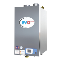
Schematic Piping Diagram
PID (3)HWD to (1)HET CWIS & TMV
WH-1
CD
CNK
WH-3WH-2
CD
CD
CD
CW
HWR
TWR
TWS
HWS
CW
HWS
HWR
TWR
TMV
HET
ET
To SystemFrom System
Make-up
Water
TS
Ball valve
Check valve
Flow direction
Pressure Relief valve
Drain valve
Air vent
Ball Valve with built-in Drain
Valve
Gas cock
Temperature Sensor
Aquastat
Floor drain
LEGEND
HWR
Hot Water Return
HWS Hot Water Supply
CD Condensate Drain
WH Water Heater with Stand
Pump
CNK Condensate Neutralizer
HET Storage Tank
Termostatic Mixing Valve
Thermometer
TMV
TWR Tempered Water Return
TWS
Tempered Water Supply
ET
Expansion Tank
CW
Cold Water
TS
Cold Water Injection System
CWIS
From TankTo Tank
CWIS
Reference dimensions are ± 10%
All dimensions are ± 1"
MM/DD/YY MM/DD/YY
1/2"=1'
Custom
Dwg No.
Customer / Job name:
Scale:
Description:
Date:Drawn/
Revised by:
Checked/
Apv. by:
Revision:
Description:
Date:Drawn/
Revised by:
Checked/
Apv. by:
Revision:
AE 12/17/10
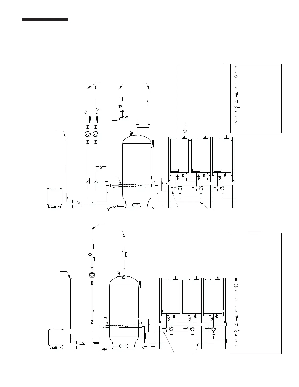
Schematic Piping Diagram
PID (3)HWD to (1)HET CWIS
HET
HWS
CW
CWIS
To System
TS
CW
HWRHWR
ET
From System
Make-up
Water
LEGEND
HWR
Hot Water Return
HWS Hot Water Supply
CD Condensate Drain
WH Water Heater with Stand
Pump
Ball valve
Check valve
Flow direction
Pressure Relief valve
CNK Condensate Neutralizer
HET
Storage Tank
Thermometer
ET Expansion Tank
Drain valve
Air vent
Ball Valve with built-in Drain
Valve
Gas cock
CW Cold Water
Temperature Sensor
Aquastat
Floor drain
TS
Cold Water Injection System
CWIS
CD
From Tank
To Tank
WH-1
CNK
WH-3WH-2
CD
CD
CD
34
PART 5. PIPING
F. WATER HEATING SCHEMATIC DRAWINGS (continued)
Three water heater schematic
to single tank with mixing
valve AND CWIS
™
Three water heater
schematic to single tank
with CWIS
™
IMPORTANT NOTE: The above are representative drawings; must conform to local codes. Consult factory for
Custom System Solutions.
 Loading...