EasyManua.ls Logo

Hamilton Home Products WGH User Manual

Hamilton Home Products WGH
24 pages
To Next Page IconTo Next Page
Page #1 background imageLoading...
Page #1 background image
THIS MANUAL IS THE PROPERTY OF THE OWNER.
PLEASE BE SURE TO LEAVE IT WITH THE OWNER WHEN YOU LEAVE THE JOB.
Inspection on Arrival
1. Inspect unit upon arrival. .
2.
Check rating plate on unit to verify that power supply meets
available electric power at the point of installation.
3. Inspect unit upon arrival for conformance with description of
product ordered (including specifications where applicable).
For technical assistance and Warranty Administration,
contact Hamilton Home Products at 1.800.879.0123. Do not
return equipment to the home center.
Table of Contents
Inspection on Arrival . . . . . . . . . . . . . . . . . . . . . . . . . . . . . . . . .1
Special Precautions . . . . . . . . . . . . . . . . . . . . . . . . . . . . . . . . . .2
SI (Metric) Conversion Factors . . . . . . . . . . . . . . . . . . . . . . . . .3
Unit Location . . . . . . . . . . . . . . . . . . . . . . . . . . . . . . . . . . . . . . .3
Combustible Material and Service Clearances . . . . . . . . .3
Unit Mounting . . . . . . . . . . . . . . . . . . . . . . . . . . . . . . . . . . .4
Unit Installation . . . . . . . . . . . . . . . . . . . . . . . . . . . . . . . . . . . . .6
Venting . . . . . . . . . . . . . . . . . . . . . . . . . . . . . . . . . . . . . . . .5
Gas Connections . . . . . . . . . . . . . . . . . . . . . . . . . . . . . . .10
Electrical Connections . . . . . . . . . . . . . . . . . . . . . . . . . . .11
Checking Input Rate . . . . . . . . . . . . . . . . . . . . . . . . . . . . .12
Unit Components . . . . . . . . . . . . . . . . . . . . . . . . . . . . . . . . . . .14
Dimensions . . . . . . . . . . . . . . . . . . . . . . . . . . . . . . . . . . . . . . .16
Service/Trouble Shooting . . . . . . . . . . . . . . . . . . . . . . . . . . . .17
Wiring . . . . . . . . . . . . . . . . . . . . . . . . . . . . . . . . . . . . . . . . . . .21
Warranty . . . . . . . . . . . . . . . . . . . . . . . . . . . . . . . . . . . . . . . . .35
INSTALLATION AND SERVICE MANUAL
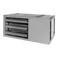
gas-fired unit heaters
model WGH
VHHP6-576.5
Part 5H76253 Rev. E
March, 2004
All models approved for use in California by the CEC, in New
York by the MEA division, and in Massachusetts. Unit heater
is certified for residential and commercial applications.
WARNING
Improper installation, adjustment, alteration,
service or maintenance can cause property
damage, injury or death, and could cause
exposure to substances which have been
determined by various state agencies to cause
cancer, birth defects or other reproductive
harm. Read the installation, operating and
maintenance instructions thoroughly before
installing or servicing this equipment.
FOR YOUR SAFETY
The use and storage of gasoline or other
flammable vapors and liquids in open
containers in the vicinity of this appliance
is hazardous.
CAUTION
To prevent premature heat exchanger failure
do not locate ANY gas-fired units in areas
where chlorinated, halogenated or acid
vapors are present in the atmosphere.
FOR YOUR SAFETY
WHAT TO DO IF YOU SMELL GAS:
1. Open windows.
2. Do not try to light any appliance.
3. Do not touch any electrical switch; do not
use any phone in your building.
4. Immediately call your gas supplier from
a neighbor’s phone. Follow the gas
supplier’s instructions. If you can not reach
your gas supplier, call your fire department.
IMPORTANT
The use of this manual is specifically
intended for a qualified installation and
service agency. All installation and service
of these units must be performed by a
qualified installation and service agency.
Hamilton Home Products, Inc.
Question and Answer IconNeed help?

Do you have a question about the Hamilton Home Products WGH and is the answer not in the manual?

Hamilton Home Products WGH Specifications

General IconGeneral
Adjustable ThermostatYes
Overheat ProtectionYes
Remote ControlNo
TimerNo
Power1500 Watts
Voltage120 Volts

Summary

Inspection on Arrival

Special Precautions

HAZARD INTENSITY LEVELS

Defines hazard classifications (Danger, Warning, Caution, Important) for user safety.

DANGER

Critical hazard warning for explosive or flammable atmospheres.

WARNING

Key safety warnings for gas heating equipment, including venting and maintenance.

CAUTION

Installation requirements and safety considerations for gas appliances.

SI (METRIC) CONVERSION FACTORS

UNIT LOCATION

DANGER

Warning against installing in explosive or flammable atmospheres.

CAUTION

Requirements for installing units in confined spaces and clearance rules.

IMPORTANT

Precaution to prevent heat exchanger failure from corrosive vapors.

Location Recommendations

Advice on considering space, supply, and venting for unit placement.

UNIT MOUNTING

CAUTION

Safety warnings and requirements for unit suspension and mounting.

UNIT INSTALLATION

CAUTION

Safety warnings regarding installation clearances and mounting methods.

Venting

WARNING

Critical warning against operating unvented and using external exhausters.

CAUTION

Installation compliance with local codes and national standards for venting.

Table 5.1 ANSI Unit Heater Venting Requirements

Table detailing venting requirements based on unit categories and condensate production.

Venting Instructions

Step-by-step procedures and guidelines for correct vent system installation.

Figure 6.1 Venting Through Combustible Wall or Roof

Diagram illustrating venting through combustible materials with different pipe types.

Figure 6.2 Vertical Venting Through Flat Roof

Diagram showing vertical venting configuration through a flat roof.

Figure 6.3 Vertical Venting Through Sloped Roof

Diagram illustrating vertical venting setup on a sloped roof.

General Instructions For Double Wall (Type B) Terminal Pipe Installation

Specific steps for installing double wall vent pipe and terminals.

Figure 7.1 Horizontal Category III Venting with Upward Pitch

Diagram for horizontal Category III venting with an upward slope.

Figure 7.2 Horizontal Category III Venting with Downward Pitch (with drip leg)

Diagram for horizontal Category III venting with downward slope and drip leg.

Figure 7.3 Horizontal Category III Venting with Downward Pitch (Condensate Drips Out End)

Diagram for horizontal Category III venting with downward slope, condensate drip.

Additional Requirements For Horizontal Category III Venting

Specific requirements for Category III horizontal venting systems.

Additional Requirements For Horizontal Category I Venting (Residential Only)

Specific requirements for Category I horizontal venting in residential applications.

Figure 8.1 Horizontal Category I Venting -TEE With Upward Pitch

Diagram for horizontal Category I venting using a TEE with upward pitch.

Table 8.1 Allowable Vent Configurations for Category I Horizontal Venting

Table listing vent configurations, allowances, and capacities for Category I horizontal venting.

Figure 9.1 Horizontal Category I Venting - Clearance to Eave

Diagrams showing clearance requirements for horizontal Category I venting to eaves.

Figure 9.2 Horizontal Category I Venting - TEE With Downward Pitch

Diagram for horizontal Category I venting using a TEE with downward pitch.

Figure 9.3 Horizontal Category I Venting - Vent Extension With Upward Pitch

Diagram for horizontal Category I venting with an upward pitch vent extension.

Figure 9.4 Horizontal Category I Venting - Vent Extension With Downward Pitch

Diagram for horizontal Category I venting with a downward pitch vent extension.

Gas Connections

WARNING

Safety warnings regarding gas piping pressure testing and gas pressure limits.

CAUTION

Precautions for purging gas lines and leak testing.

IMPORTANT

Precaution to prevent heat exchanger failure from over-firing.

Table 10.1 Gas Pipe Capacities

Table showing allowable gas pipe sizes based on capacity and length.

Figure 10.1 Recommended Sediment Trap/Manual Shut-off Valve Installation

Diagram illustrating the correct installation of sediment traps and shut-off valves.

Wiring

WARNING

Safety warnings about disconnecting power and following wiring diagrams.

CAUTION

Requirements for electrical grounding and wire temperature ratings.

OPERATION

Procedures for pre-operational checks and safety before starting the unit.

FOR YOUR SAFETY READ BEFORE OPERATING

Crucial safety information and steps to take if gas is smelled.

OPERATING INSTRUCTIONS

Step-by-step guide for safely operating the unit.

TO TURN OFF GAS TO APPLIANCE

Procedure for safely shutting off the gas supply to the appliance.

CHECKING INPUT RATE

CAUTION

Warning about checking gas inlet pressure and potential damage from over-firing.

Input Adjustments

Guidance on adjusting gas pressure regulators for correct input.

Table 12.1 Meter-timing Gas

Table for calculating gas input using meter timing based on gas consumption.

Figure 12.1 Dials of Typical Gas Meter

Illustration of typical gas meter dials used for input rate calculation.

(B) Pressure Method

Alternative method for determining input rate by measuring gas manifold pressure.

Table 13.1 Manifold Pressure & Gas Consumption

Table correlating manifold pressure with gas consumption for different models.

Table 13.2 Orifice Drill Sizes with Decimal Equivalents

Table mapping orifice drill sizes to their decimal equivalents.

UNIT COMPONENTS

Figure 14.1 Major Gas, Electrical Service, Safety and Other Components

Labeled diagram of the unit's key internal parts and external connections.

Figure 15.1 Unit Heater Rear View

Diagram showing the rear view of the unit with identified components.

Figure 15.2 Unit Heater in Standard Mounting Configuration

Illustration of the unit in its standard factory mounting orientation.

Figure 15.3 Unit Heater Turned 180°

Illustration showing the unit after being rotated 180 degrees.

DIMENSIONS / GENERAL PERFORMANCE DATA

Dimensions (inches)

Table providing detailed physical dimensions for different model sizes.

Performance

Table detailing performance data like input, output, airflow, and heat throw.

Mounting

Information on mounting bracket compatibility with ceiling joists.

Clearances to Combustibles

Table specifying required clearances from the unit to combustible materials.

Control Codes

Table listing control codes, voltage, and gas type for unit configurations.

CONTROL OPERATING SEQUENCE

For Hot Surface Ignition

Detailed description of the ignition and burner operation sequence.

SERVICE / MAINTENANCE / TROUBLESHOOTING

WARNING

Warning about using only factory-approved parts and qualified personnel.

CAUTION

Precautionary advice regarding servicing and handling wet controllers.

IMPORTANT

Note to refer to specific sections for troubleshooting remedies.

General Maintenance

Annual maintenance tasks for the unit and venting system.

Service Instructions – Safety Devices

Instructions for checking and troubleshooting safety devices like limit controls and pressure switches.

Limit Control (Overheat Switch)

Explanation of the limit control's function and troubleshooting steps.

Flame Rollout Switch (or Switches)

Information on the flame rollout switch, its function, and troubleshooting.

Pressure Switch

Details on the pressure switch operation and troubleshooting steps.

Hot Surface igniter

Information on the hot surface igniter, its function, and replacement procedure.

LED Diagnostic Capability

Explanation of LED diagnostic codes for troubleshooting the control system.

FOR SERVICE

Guidance on seeking professional service and providing unit information.

Serial Number Designations

Explanation of how to interpret serial number designations for unit identification.

Replacement Parts

Instructions on how to order replacement parts.

Table 20.1 Troubleshooting

A table listing common unit problems, their causes, and possible remedies.

UNIT WIRING

Wiring Diagram Selection

Guidance on selecting the correct wiring diagram based on the unit's series identity number.

Figure 21.1 Unit Heater Wiring Diagram (Series 101 & 102)

Wiring diagram specific to units with series identity 101 and 102.

Figure 22.1 Unit Heater Wiring Diagram (Series 103)

Wiring diagram specific to units with series identity 103.

HAMILTON HOME PRODUCTS, INC. LIMITED WARRANTY (Residential Use Only)

WHAT THIS WARRANTY COVERS

Specifies the defects in material and workmanship covered by the warranty.

WHAT THIS WARRANTY DOES NOT COVER

Lists conditions and situations explicitly excluded from warranty coverage.

WHO THIS WARRANTY COVERS

Defines who is covered under the warranty terms.

HOW LONG THE WARRANTY LASTS

Outlines the duration of warranty coverage for different parts of the unit.

WHAT HAMILTON WILL DO TO CORRECT ANY PART OR EQUIPMENT FAILURES DURING THE WARRANTY PERIOD

Explains Hamilton's commitment to providing replacement parts for valid warranty claims.

WHAT HAMILTON WILL NOT DO

States what Hamilton will not cover, such as labor costs for repairs.

INCIDENTAL AND CONSEQUENTIAL DAMAGES DISCLAIMED

Disclaims coverage for incidental or consequential damages.

HOW STATE LAW RELATES TO THIS WARRANTY

Explains how state laws may affect warranty rights.

COMMERCIAL WARRANTY

Heat Exchangers

Warranty terms specific to heat exchangers for various product types.

Burners

Warranty terms specific to burners for different heater types.

All Other Components Excluding Heat Exchanger (Condenser), Burner, and Sheet Metal

Warranty terms for all other components not specifically listed.