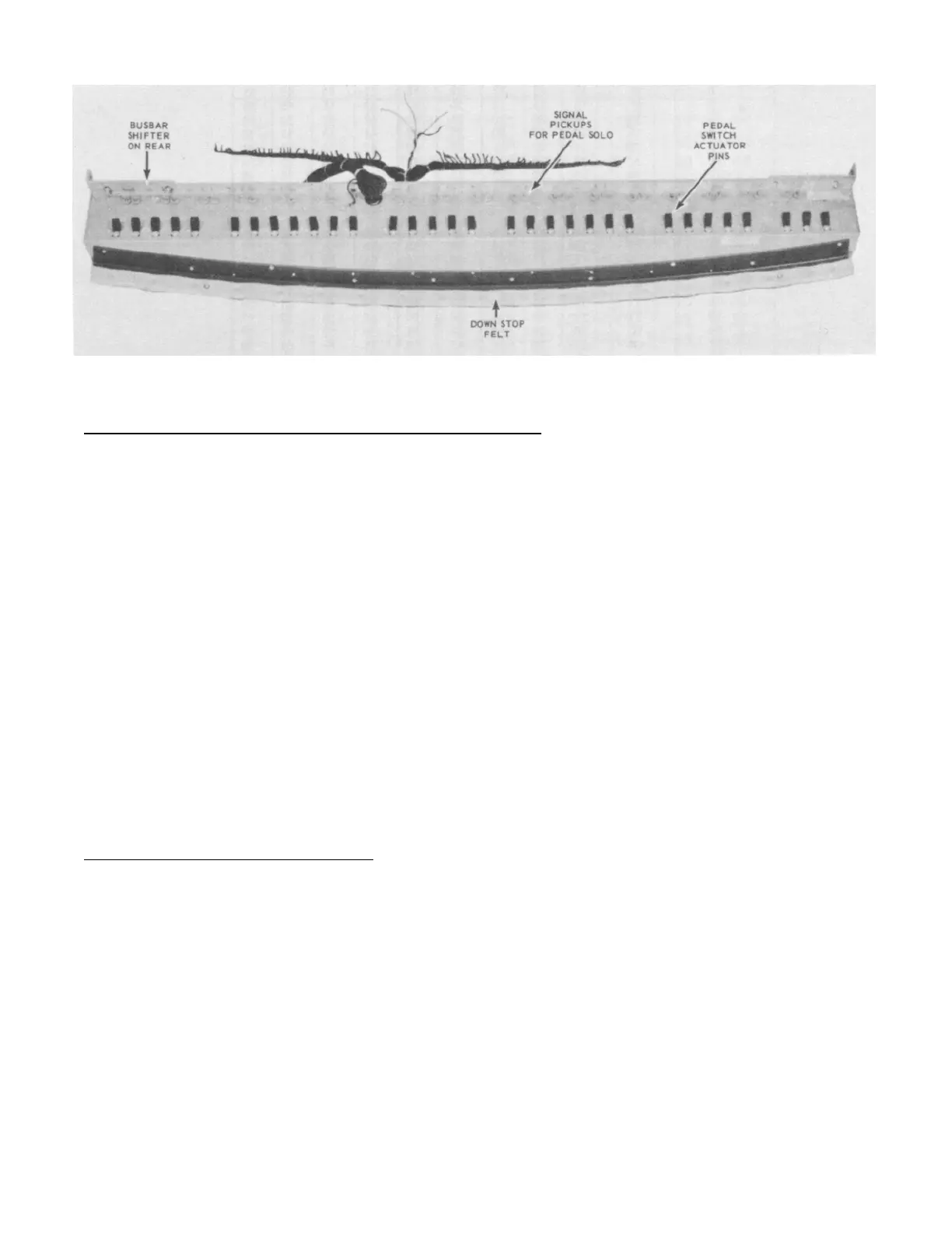
Figure 21: Concert style, 32 note pedal assembly
Pedal Switch Assembly - RT, RT-2, RT-3, and D-100
The pedal switch (shown in figure 21) is similar in internal construction to the
manuals (figure 22). Each of the 32 pedals actuates a set of contact springs,
making nine contacts available for each note. Each note consists of a fundamental
and a number of harmonics, no sub-harmonics being used. The pedal contact springs
are connected to terminals by resistance wires similar to those used in the manual
assembly, and a cable connects these terminals to the proper terminals on the
generator terminal strip. Only seven contacts are used for the mechanical generator
notes, the other two contacts are used by the pedal solo unit as explained later in
this book.
Four colored wires carry the pedal tones from the busbars to the pedal drawbars.
The wires are connected first to a resistor panel on the back of the manual
assembly. A small choke coil and resistor mounted on the manual assembly are wired
to the lower drawbar (see figure 23) and serve to filter out any higher harmonics or
transients which might be present in the lower pedal frequencies.
Figure 24 is a wiring chart for the pedals, showing the frequency numbers appearing
on each pedal contact.
Pedal Switch Assembly - Model E
Nine busbars are used in the Model E pedal switch assembly. Figure 12 illustrates
the arrangement of these busbars and the nine contact springs of a typical pedal
key. There are 32 pedal keys, and four pedal toe pistons. These pedal toe pistons,
which correspond to the preset pistons of the manuals, also have nine contact
springs touching the same nine busbars and have a locking arrangement by which only
one piston remains in operation at one time.
11