Do you have a question about the Hammond L series and is the answer not in the manual?
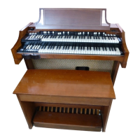
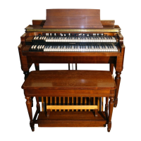
Describes the basic operational principles of L-100 Series organs.
Explains the tone generation process using tone wheels and magnets.
Details the synchronous motor drive and the main power switch.
Describes the tone generator assembly, tone wheels, and filters.
Explains the function of the upper and lower manuals and key contacts.
Details how drawbars control tone color by mixing harmonics.
Explains the function of the center drawbar for pedal volume.
Describes the 13-note pedal keyboard and its connection to frequencies.
Explains the expression pedal's role in controlling overall volume.
Lists and describes the 17 control tabs affecting organ operation.
Explains the 4 preset tabs for the upper manual and 2 for lower.
Details the 3 tabs controlling different degrees of vibrato effect.
Explains the tabs for controlling reverberation levels and overall volume.
Describes the 4 percussion control tabs and their effects on tone.
Details the additional percussion features of the L-100A model.
Explains the function of the selector switch for harmonic routing.
Describes harmonic busbar switching and reiteration split for the upper manual.
Details the six-voice percussion feature added to the L-100-1 model.
Specifies the location of rhythm controls on the lower manual end block.
Lists the available percussion voices like Block, Cymbal, Brush, etc.
Explains how to operate the percussion voices using push buttons and tabs.
Mentions support for extension speakers, inputs, and earphones.
Details the use of Hammond Tone Cabinets as extension speakers.
Explains how to connect external sound sources like record players or radios.
Describes the circuit for using earphones, silencing the main speakers.
Overviews amplifier chassis and percussion attachments in L-100 instruments.
Explains how the preamplifier receives and processes signals.
Details the vibrato system's phase shifting mechanism using tubes and reactors.
Describes the percussion amplifier's role in shaping and fading percussion tones.
Explains signal amplification and reverberation stages after expression control.
Details the 5U4 rectifier tube and filtering circuit in the power supply.
Explains the specific circuitry for L-100A percussion voicing.
Describes how the mode switch affects percussion voices and vibrato effects.
Explains the frequency divider used to create the 1-1/4 harmonic for chime tones.
Details how the Cymbal-Brush switch enables brush effect keying and cymbal effect.
Explains the circuit for keying the brush effect using the 8th harmonic busbar.
Describes the circuit for cymbal keying triggered by pedal signals.
Details the amplification of brush and cymbal signals and their connection to the overall level control.
Explains the power supply voltages for the rhythm unit.
Covers the circuitry specific to the L-100-1 six-voice percussion.
Provides details on the power supply components and their location.
Explains the operation of push-button circuits for triggering voices.
Details the keying circuits for the lower manual keys.
Explains the pedal keying circuit that triggers selected voices.
Introduces disassembly techniques specific to L-100 Series organs.
Notes requirements for removing top, back, or both for access.
Step-by-step guide for removing upper manual keys.
Step-by-step guide for removing lower manual keys.
Instructions for removing drawbar contact springs.
Procedure for removing drawbars, knobs, or the entire assembly.
Detailed steps for removing the upper manual assembly.
Detailed steps for removing the lower manual assembly.
Instructions for disconnecting and removing the generator.
Steps for disconnecting and removing the motor.
Guide for removing the pedal keyboard assembly.
Steps for removing the swell assembly and its components.
Procedure for replacing a broken tab on a switch.
Instructions for replacing the pilot light bulb or power switch.
Notes on accessing L-100A percussion circuitry on the end block.
Identifies locations of L-100-1 percussion and power supply components.
Outlines performance standards, adjustments, and troubleshooting info.
Steps to prepare the organ for performance checks.
Lists essential equipment like VTVM and oscilloscope.
Detailed steps for checking organ performance and output voltages.
Instructions for testing vibrato effect using listening and oscilloscope methods.
Checks for L-100A percussion unit, including selector and mode switch operations.
Performance checks and troubleshooting for L-100-1 six-voice percussion.
Guide for adjusting rhythm volume levels using VTVM.
Steps to diagnose a silent voice, checking connections and voltages.
Diagnosing issues where a voice doesn't play from its programmed source.
Addresses situations where all percussive voices are silent.
Diagnosing when hiss voices are silent but percussive voices work.
Checks for issues with pedal keying pulse circuits.
Checks for issues with manual keying pulse circuits.
Checks percussion power supply connections and outputs.
A general heading for troubleshooting issues.
Diagnosing why the entire organ is not producing sound.
Addressing issues with individual keys or missing harmonics.
Diagnosing weak notes due to contacts, connections, or filters.
Addresses weak, absent, or improperly decaying percussion notes.
Explains the pedal cipher issue and how to release it.
Discusses causes and solutions for hum in the speaker output.
Guidance on replacing vacuum tubes used in the organ.
States that this section contains schematic diagrams for servicing.
Lists parts for the control panel assembly.
Lists parts for the lower manual assembly.
Lists parts for the upper manual assembly.
Lists parts for generator and motor assemblies.
Lists parts for the pedal keyboard and switch assembly.
Lists components for the AO-42 preamplifier assembly.
Lists components for the AO-47 vibrato amplifier assembly.
Lists various parts for power amplifier assemblies.
Lists parts for the swell pedal assembly.
Lists parts for the rhythm II and extrusion assembly.
Lists parts for the power supply assembly.
Lists various miscellaneous parts for the organ.
Lists parts related to the organ's woodwork and cabinet.
| Type | Tonewheel Organ |
|---|---|
| Manuals | 2 |
| Vibrato/Chorus | Yes |
| Percussion | Yes |
| Reverb | No |
| Amplifier | Built-in |
| Speakers | Built-in |
| Models | L-100, L-101, L-111, L-122 |
| Pedals | 13 |
| Drawbars | Yes |