7. Identify the green and black wires on the center speaker that connect to the
AO-35 or AO-44 amplifier. Remove these wires and connect the green wire to the GN
speaker terminal and the black wire to the BN -BK speaker terminal on the AO-39
amplifier.
8. Identify the speaker terminals on the reverberation amplifier AO-35 or AO-44.
If a black wire is soldered to the left speaker terminal on the amplifier, reverse
the speaker leads at the amplifier so that the gray wire is on the left lug and the
black wire is on the right lug of the amplifier speaker terminals.
9. Remove the blue wire that is connected to the speaker directly above the
reverberation amplifier. Splice on an additional length of wire long enough to reach
the earphone jack.
10. Solder a wire to the empty lug on the speaker long enough to reach the earphone
jack.
11. Solder a wire to the right speaker terminal long enough to reach the earphone
jack. (This terminal is grounded inside the AO-35 or AO-44 chassis. )
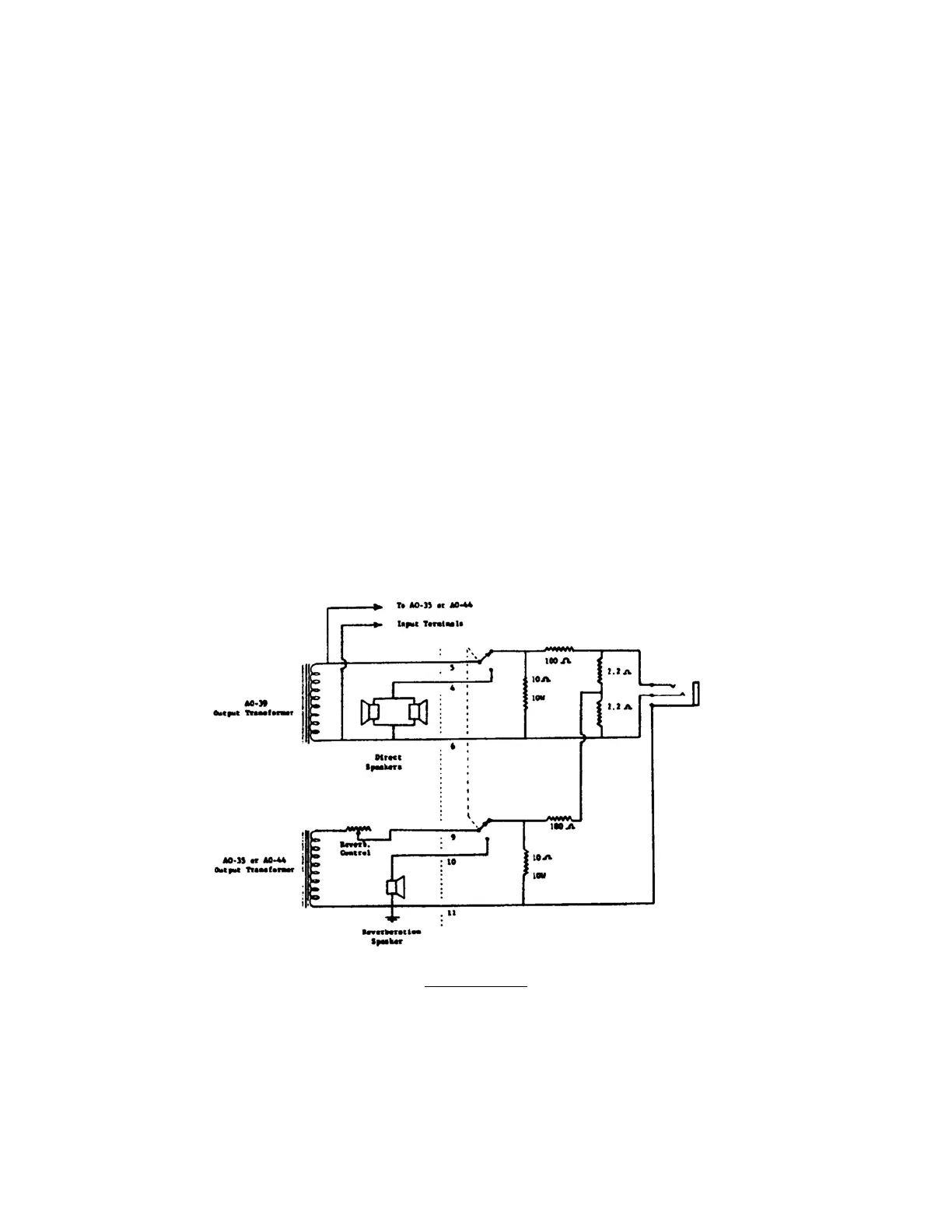
12. Mount all components to the right of the dotted line shown on the diagram
in a suitable box and connect as shown. Numbers shown under wires identify these
leads based on the preceding steps.
13. Mount box containing switch and earphone jack at a convenient point at the
front of the console.
PHONO INPUT
A microphone or record player pickup may be used through the organ if desired.
The preamplifier is equipped with a standard phonograph input jack. The input
impedance is approximately 1 megohm and the circuit requires a maximum input
signal of about ½ volt. A volume control will have to be installed between the
microphone or record player input and the organ inasmuch as the swell control of the
organ does not affect this input.
7