Should it be necessary to remove the carbon brush audio pick-up assembly (J),
desolder the audio wire from the brush assembly and remove the two (2) screws (K). To
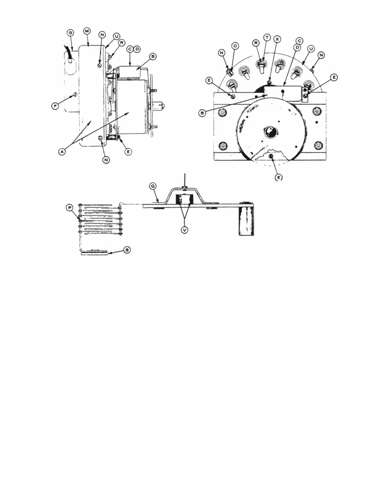
remove the end brush (I) remove screw (L) and separate from the brush assembly.
7. Remove the four (4) screws (N) and slip the housing cover (M) off the main
assembly. Note: Mark the housing cover (M) and the main assembly chassis (U) to
indicate the starting point of the scanner cable, also mark the location of the cable
clip (O).
8. Stationary plates (P) and rotor (Q) are mounted on the main assembly chassis (U).
Remove two (2) of the stationary plates (P), by removing screws (R). When removing
the stationary plates from the assembly you will notice that there are insulator (S)
and (T) on both sides of the main assembly chassis, insulating the stationary plates
from the assembly (U). Then remove the rotor assembly (Q) by loosening the two (2)
Bristol type set screws (V), to avoid damaging the rotor contact pin during
disassembly.
29