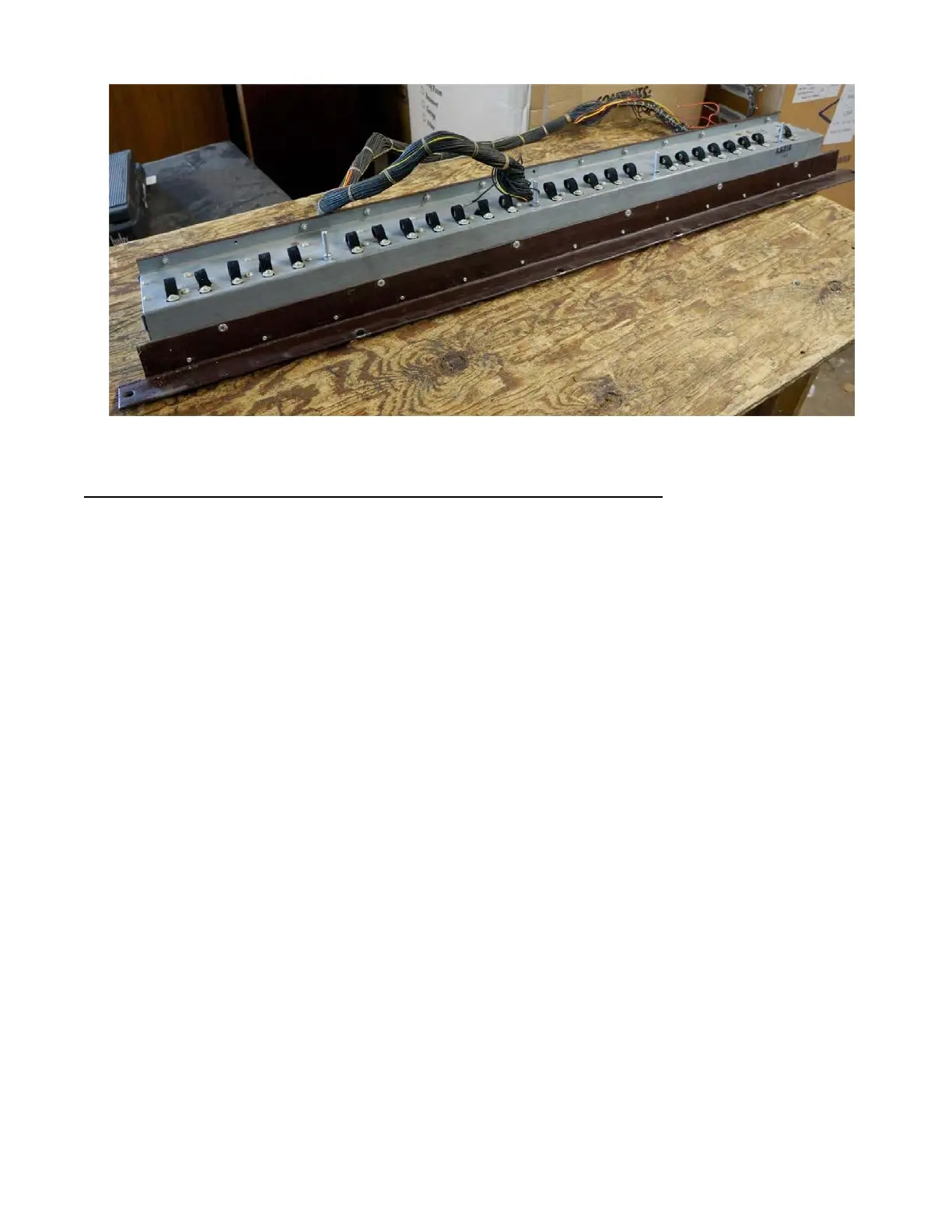
Figure 5: Typical 25 note pedal assembly
Pedal Switch Assembly - All Models with 25 Note Pedal Keyboard
The pedal switch (shown in figure 5) is similar in construction to the manuals
except that only four busbars are included instead of nine. Each of the 25 pedals
actuates a double set of contact springs, making eight contacts available for each
note. Each note consists of a fundamental and number of harmonics, no sub-harmonics
being used. The pedal contact springs are connected to terminals by resistance wires
similar to those used in the manual assembly, and a cable connects these terminals
through a wiring tube to the proper terminals on the generator terminal strip.
Four colored wires carry the pedal tones from the busbars to the pedal drawbars.
In some models the wires are connected first to a resistor panel on the back of the
manual assembly. A small choke coil and resistor mounted on the manual assembly are
wired to the lower drawbar (see figures 8, 9, 10, 11) and serve to filter out any
higher harmonics or transients which might be present in the lower pedal
frequencies.
Early consoles used only seven contacts on each pedal (see figure 6) and were
wired so that any harmonic would appear on only one pedal drawbar (figures
8 and 9). Later consoles use all eight contacts (figure 7) and employ a system for
mixing the 16 ft. and 8 ft. tones (figures 10 and 11). The harmonic arrangement of
the contacts is also different in these later units.
Figure 13 is a wiring chart for the pedals, showing the frequency numbers appearing
on each pedal contact. The variations in wiring make the pedal switches match the
different types of generators described in the section covering tone generators, and
therefore the various types are not interchangeable.
Specific pedal wiring of any console can be determined by obtaining the serial
number and referring to figures 8 to 11. Included in these sketches are references
to figure 13 wiring chart.
6