If there are wires with different colors, have this unit installed by qualified licensed electrician.
e. Push all connected wires up into junction box.
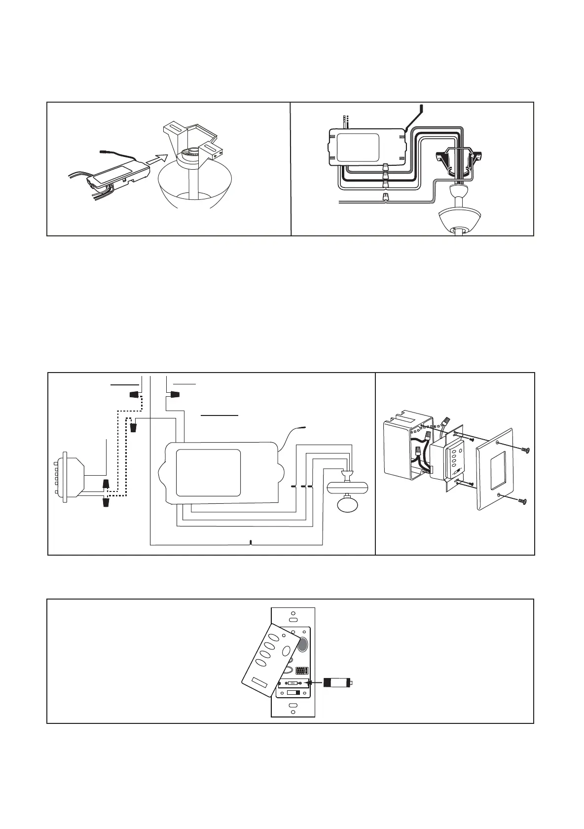
f. Lay the black antenna wire on top of the receiver, and put the receiver in the mounting bracket. (Fig. 3)
g. Reinstall all canopy on the mounting bracket
h. Restore electrical power.
WARNING! HOOK UP “IN SERIES” ONLY. DO NOT CONNECT NEUTRAL SUPPLY WIRE OF ELECTRIC CIRCUIT TO THE
TRANSMITTER WALL SWITCH, DAMAGE TO THE TRANSMITTER WALL SWITCH AND POSSIBLE FIRE COULD OCCUR.
a. Remove the existing wall plate and switch from the wall outlet box.
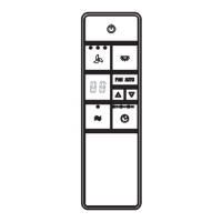
b. Make the electrical connections as shown in Fig. 4. If your outlet box has a ground wire (Green or Bare Copper) connect the
transmitter’s ground wire directly to one of the screws from the outlet box. Secure all wire connections with the plastic wire nuts
provided.
c. Carefully tuck the wire connections inside the outlet box. Use the screws provided to secure the wall transmitter and wall plate to the
outlet box. (Fig. 5)
Fig. 4 Fig. 5
WALL
CONTROL
BLACK
BLACK
BLACK
BLACK
BLACK
WHITE
BLUE
BLUE
GROUND
GROUND
GREEN
INPUT
AC120V
AC SUPPLY
BLACK
BLACK
BLACK
WHITE
WHITE
WHITE
GREEN
HI
MED
LOW
FAN OFF
ON ECE
1 2 3 4
ON
D
LIGHT
23AE 12V
Fig. 6
RECEIVER
Fig. 2 Fig. 3
AC SUPPLY
BLACK
WHITE
BARE GREEN
WHITE
WHITE
BLUE BLUE
BLACK
BLACK
RECEIVER
3. INSTALLING THE WALL TRANSMITTER
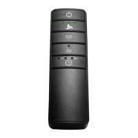
d. Remove cover by snapping off from top or bottom, install 12V battery located in the wall transmitter, Duracell MN21/Eveready A23/GP
23A all 12V. (Fig. 6)