Assembly and Installation (Continued)
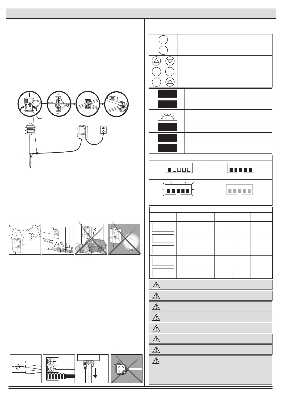
□ Place the wire connector (G) on opposite sides of the low
voltage cable (P) where the xture will be located.
□ Align and t the main low voltage cable (P) vertically to the
slot of wire connector (G) as shown.
□ Press the wire connector (G) together until fully seated and
locked around the cable (P). Pre-set prongs will pierce the
cable insulation and establish contact. Turn on the power unit.
If the light xture does not turn on, repeat previous steps.
□ Once the clip-on connector (G) is in place, wrap it with
electrical tape for additional protection.
□ CAUTION BE CAREFUL! THE WIRE STABS ARE VERY SHARP!
□ After all xtures are installed, turn on the transformer.
□ This transformer is weatherproof and suitable for outdoor and
indoor use.
□ Install the transformer (O) at a level where the controls are
visible and accessible.
□ Do not install behind shrubs. It will affect the dusk-to-dawn
photocell for Auto mode.
□ Photocell will not operate properly if installed too close to a
nighttime light source.
□ MOUNT AT LEAST 12 INCHES (30CM) ABOVE GROUND
□ Open the front panel and remove the plastic plate by pulling on it.
□ Remove the landscape wire (P) insulation 1/2 in. from both
wires and twist ends.
□
Insert wires under each terminal plate on the transformer (O)
and tighten screws.
□ Gently pull on the landscape wire to verify if the connection is
strong.
□ Verify that there are no loose cable strands.
□ Replace the plastic plate and close the panel.
G
4
Installing the transformer
5
Connecting the cable to the transformer
O
12 in. (12.7 mm)
P
1/2 in. (12.7 mm)
PULL
O
P
6
How to operate the transformer controls
WARNING: To reduce the risk of FIRE OR INJURY TO PERSONS:
WARNING: Do not install within 10 ft. (3 m) of a pool, spa or fountain.
WARNING: There are no serviceable parts inside the power supply unit. DO
NOT DISASSEMBLE.
WARNING: Do not submerge the transformer.
WARNING: Do not connect two or more transformers in parallel.
WARNING: Do not use with a dimmer.
CAUTION: Plug the power supply unit directly into a GFCI outlet that is marked
“wet location”.
The maximum output of this transformer is 120 watts. Do not
overload the transformer. Be sure that the total cumulative wattage of all 12 volt
xtures connected to the transformer is equal to or less than 120 watts. This garden
light system must be installed in accordance with all local codes and ordinances. If
you are experiencing problems, contact a qualied electrician. WARNING: For use
with 12 volt low voltage outdoor landscape lighting system only. Not for use with
submersible light or pool/spa equipment.
WARNING: Do not use an extension cord.
□ SAFE
PHOTOCELL
Mount the transformer
□ Option 1: Standard wall mounting
Insert the two (2) included support screws 3.5” (9 cm) apart in a wall
near an electrical outlet and mount the transformer.
□ Option 2: Brick or cement wall mounting
Drill two (2) holes of 5/16” (8 mm), 3.5” (9 cm) apart from each other,
in a wall near an electrical outlet and place the two (2) plastic
anchors included. Insert the two (2) support screws in the anchors
until they have about 1/4” (6 mm) of space left to mount the
transformer.
Press to conrm a selection.
Press to modify or change a mode. Press it to exit any
settings without saving.
Press these to select and go through the interface.
Press at the same time to change time and date. *Necessary for
Timer, Auto and Sunwise settings to work properly.
Press at the same time to change Sunwise time zone.
*Necessary for optimal Sunwise mode.
/
+
+
ENTER
ENTER
MODE
MODE
MODE
The time at which the lights will turn On. This step comes
after selecting a Mode. (Shows up for Timer Mode only)
The time at which the lights will turn Off. This step comes
after selecting a Mode. (Auto, Timer and Sunwise only)
Select this to close the lights at dawn. When selecting an end
time, scroll using up and down until the icon shows up (Auto
and Sunwise only)
NORTH zone
Refers to locations from north of Chicago, IL.
CENTRAL zone
Refers to locations between Chicago, IL and southern Missouri.
SOUTH zone
Refers to locations south of Missouri.
START
END
NORTH
SOUTH
CENTRAL
Less than 20%: Normal Less than 100%: Normal
Over 120%, shuts down
reduce load
Blinking:
Overloaded over 100%
LOADLOAD
LOADLOAD
Safety mesure of current consumption
Recommended Control Settings
Modes Functionality Outdoor Indoor
Dusk-to
Dawn
Always ON YES YES NO
Always OFF
YES YES NO
Fixed start and end time
YES YES NO
Uses the light sensor
(photocell) to Open/Close
the lights
YES NO YES
Astronomical timer auto-
matically adjusts to local
sunrise/sunset times
YES YES YES
ON
OFF
TIMER
AUTO
SUNWISE
*The channels will only turn on at the exact start time selected for Timer and dusk for Sunwise.
 Loading...