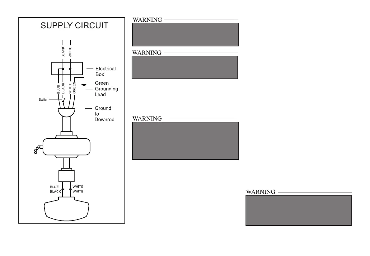
7.
CHECK TO SEE THAT ALL CONNECTIONS ARE
TIGHT, INCLUDING GROUND, AND THAT NO
BARE WIRE IS VISIBLE AT THE WIRE NUTS, EX-
CEPT FOR THE GROUND WIRE.
ELECTRICAL DIAGRAMS ARE FOR REFERENCE
ONLY. OPTIONAL USE OF ANY LIGHT KIT SHALL
BE UL LISTED AND MARKED SUITABLE FOR
USE WITH THIS FAN.
Figure 13
Finishing the Fan
Installation
STANDARD CEILING MOUNTING
1. Align the locking slots of the ceiling canopy
with the two screws in the mounting bracket.
Push up to engage the slots and turn clock-
wise to lock in place. Immediately tighten
the two mounting screws rmly.
2. Install the remaining two mounting
screws into the holes in the canopy and
tighten rmly.
WHEN USING THE STANDARD BALL/DOWN-
ROD MOUNTING, THE TAB IN THE RING AT THE
BOTTOM OF THE MOUNTING BRACKET MUST
REST IN THE GROOVE OF THE HANGER BALL.
FAILURE TO PROPERLY SEAT THE TAB IN THE
GROOVE COULD CAUSE DAMAGE TO WIRING.
3. Install the decorative canopy ring by align-
ing the ring’s slots with the screws in the
canopy. Rotate the ring counter-clockwise
to lock in place.
4. You may now proceed to attaching the
fan blades.
CLOSE-TO-CEILING MOUNTING
1. Carefully unhook the fan from the mount-
ing bracket and align the locking slots of the
ceiling canopy with the two screws in the
mounting bracket. Push up to engage the
slots and turn clockwise to lock in place. Im-
mediately tighten the two mounting screws
rmly.
2. Install the remaining two mounting screws
into the holes in the canopy and tighten
rmly.
3. Install the decorative canopy ring by align-
ing the ring’s slots with the screws in the
canopy. Rotate the ring counter-clockwise
to lock in place.
4. You may now proceed to attaching the fan
blades.
LOCKING SLOTS OF CEILING CANOPY ARE
PROVIDED ONLY AS AN AID TO MOUNTING. DO
NOT LEAVE FAN ASSEMBLY UNATTENDED UN-
TIL ALL FOUR CANOPY SCREWS ARE ENGAGED
AND FIRMLY TIGHTENED.