4
SUCTION LINE
A 1” (25 mm) suction line should be connected to a suction
accumulator, see Figure 3. The purger evaporator shell
temperature sensor is factory set at 40°F (4°C). To allow for
temperature transfer losses between the purger evaporator
and the temperature sensor, the suction temperature
should be approximately 20°F (–7°C) or below. This then
switches the AUTO-PURGER Plus from 3333 EVAP TEMP
>40F (4C) to COLLECTING AIR/WATER mode. For higher
suction temperatures, consult the factory.
RELIEF VALVE VENT LINE
A relief valve vent line should be connected to appropriately
vent any potential relief valve discharge in accordance with
applicable codes, for example ANSI/ASHRAE Standard 15,
Safety Standard for Refrigeration Systems, see Figure 6.
WATER BUBBLER FILL LINE
An automatic water bubbler flush system is provided
with the purger. A water line must be connected to the
water bubbler fill line solenoid valve (D), see Figure 6. The
connection is ½” FPT. The water supply pressure should
be 30–80 psig (2.1–5.5 barg).
LOW-PRESSURE PUMPED-LIQUID LINE
A ½” (13 mm) low-pressure pumped-liquid source is
required for the AUTO-PURGER Plus. This connection
should be from the pump discharge of the lowest pressure
recirculator, see Figure 3. This connection should be at a
location where oil will not be directed into the purger. The
low-pressure pumped-liquid line feeds makeup liquid as
required during purging. The line contains liquid ammonia
that typically is also contaminated with water which is to
be removed by the AUTO-PURGER Plus. The liquid line
solenoid valve (B) on the AUTO-PURGER Plus closes when
the AUTO-PURGER Plus is off, see Figure 6.
If the system contains more than one vessel that does
not feed liquid to any other lower pressure vessel,
then separate pipes may need to be installed, with
corresponding shutoff valves, so that liquid can periodically
be drawn from each vessel which may contain water. The
liquid pressure must be a minimum 15 psi (1.0 bar) higher
than the APPT suction for the liquid to feed properly.
LOW-PRESSURE LIQUID RETURN LINE
A ½” (13 mm) low-pressure liquid return line is required
for the AUTO-PURGER Plus. Ammonia vapor from the
foul gas line is condensed to liquid in the air separator
chamber. This condensed liquid ammonia flows to the
suction accumulator through the low-pressure liquid
return line, see Figure 3.
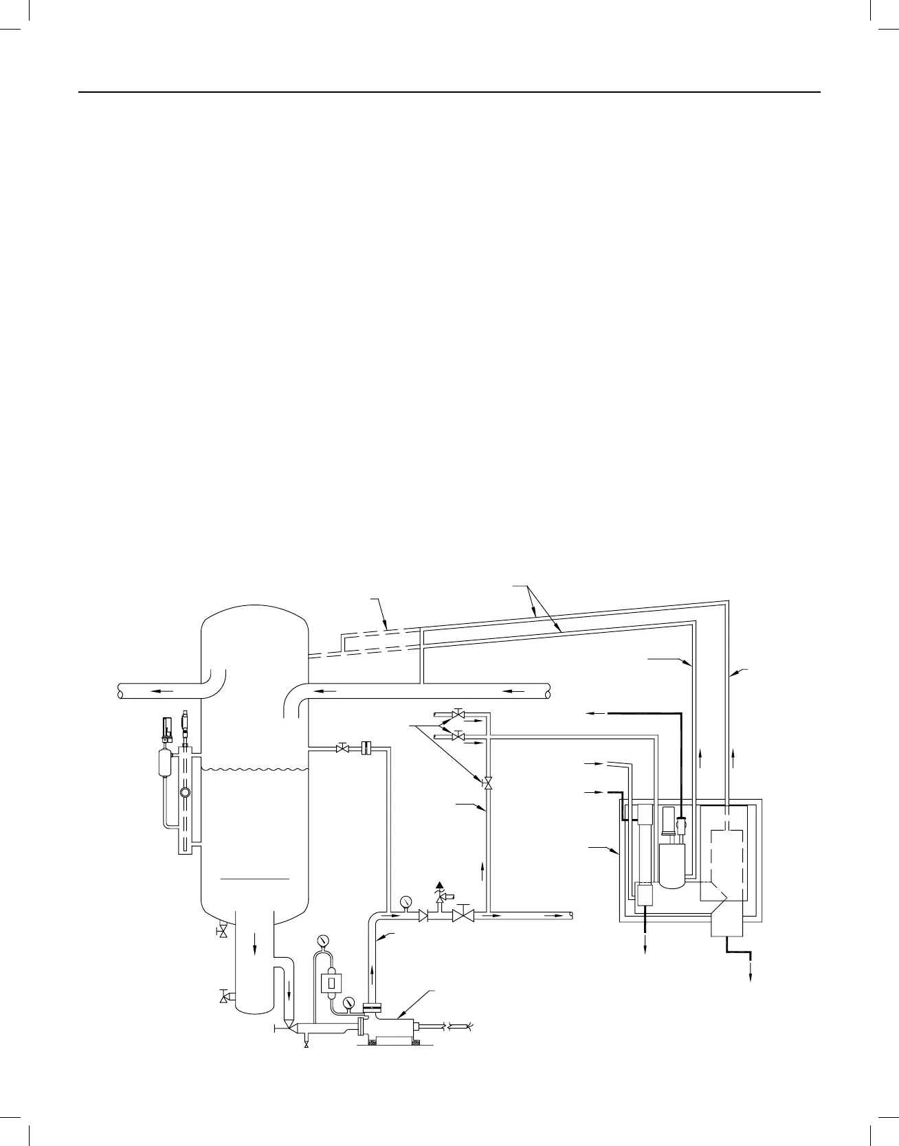
AUTO-PURGER PLUS APPT PIPING DIAGRAM
Figure 3
TO COMPRESSORS FROM EVAPORATORS
PUMP
DISCHARGE
LINE
TO SYSTEM
FILL LINE
WATER BUBBLER
DRAIN LINE
WATER BUBBLER
FROM PURGE POINTS
FOUL GAS LINE
LINE
WATER PURGE
VENT LINE
RELIEF VALVE
PUMPED
LIQUID LINE
SUCTIO
LINE
LOW PRESSURE
LIQUID RETURN LINE
REFRIGERANT PUMP
OPTIONAL
PIPING
PITCH LINES TOWARD
RECIRCULATOR
AUTO-PURGER
PLUS
SHUT-OFF VALVES
TO SWITCH FROM
MULTIPLE VESSELS
LOWEST PRESSURE
RECIRCULATOR
This drawing is for illustration purposes only
and should not be used for actual engineering
or installation. Not to scale.
Note: For APPT piping diagram to controlled pressure receiver (CPR) system, request Hansen sales drawing #2003-04.
SECTION 2 INSTALLATION
 Loading...