10
F100d
JAN 2011
HOT GAS DEFROST NOMINAL VALVE SIZING (TONS)
REFRIG. APPLICATION
PORT SIZE
3/4” 1” 1-1/4”
1-1/2”
2” 2-1/2”
R717
Hot Gas Solenoid 9 to 15 15 to 28 28 to 39 39 to 73 73 to 106 106 to 165
Defrost Relief Regulator 17 to 24 24 to 45 45 to 60 60 to 96 96 to 140 140 to 225
R22
Hot Gas Solenoid 6 to 8 8 to 15 15 to 20 20 to 32 32 to 47 47 to 75
Defrost Relief Regulator 6 to 8 8 to 15 15 to 20 20 to 32 32 to 47 47 to 75
Evaporator tons at 10ºF (5°C) temperature differential. Ideal sizing could vary with desired time for defrosting,
available supply pressure, amount of ice on evaporator, usage of pre-defrost pumpout, etc. For other control
valve sizing, see detailed Hansen bulletins on specific valve types.
VALVE SELECTION
* Type HCK2, HCK2W requires single pilot solenoid valve to operate and has minimal internal bleed to down stream side of main
valve. Type HS9B, HS9BW uses dual pilot solenoid valve assembly and has no internal bleed.
HT100 CONDENSATE
DRAINER
This unit is ideally suited for the
removal of liquid condensate from
hot gas mains and headers. Helps
assure refrigerant gas will be available at inlet of hot
gas supply valve leading to evaporator. This avoids
moving condensed liquid through valve before frost
melting can begin. Typical rating at 86ºF to 10ºF is
7.5 lbs./min. (0.063 kg/sec.) for ammonia and 24.5 lbs./
min. (0.117 kg/sec.) for R22. For greater capacities,
contact factory. Inlet/outlet connections: combination
¾” FPT/1”Weld.
HD101 DEFROST
CONDENSATE LIQUID
DRAINER
Mechanical/non-electrical float
regulator drains liquid condensate
from evaporator during defrost. It
has built-in gas vent plus expansion valve bypass as
is necessary to avoid gas binding. Suitable capacity
for 42 ton (147 kW) max. ammonia evaporator or 11
ton (39 kW) max. R22 evaporator; for larger capacities,
contact factory. Inlet/outlet connections: combination
¾” FPT/1” Weld.
DESCRIPTION
PORT SIZES
1/2” 3/4” 1” 1-1/4” 1-1/2” 2” 2-1/2” 3” 4” 5” 6”
Liquid Line Solenoid
Valve
HS8A
HS7
HS4A
HS7
HS4A
HS7
HS4A
HS4A HS4A HS4A − − − −
Suction
Line
Solenoid
Valve
Down
to -20ºF
(-30ºC)
−
HS7
HS4A
HS7
HS4A
HS7
HS4A
HS4A HS4A HS4A HS4A HS4A HS4W HS4W
Down
to -60ºF
(-50ºC)
Gas-
Powered
(Normally
Open)*
− − − HCK2 HCK2 HCK2 HCK2 HCK2 HCK2 HCK2W HCK2W
− − − HCK5 HCK5 HCK5 HCK5 HCK5 HCK5 HCK5W HCK5W
− − − HS9B HS9B HS9B HS9B HS9B HS9B HS9BW HS9BW
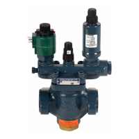
Hot Gas Line
Solenoid Valve
HS8A
HS7
HS4A
HS7
HS4A
HS7
HS4A
HS4A HS4A HS4A − − − −
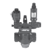
Defrost Relief
Regulator
− HA4AK HA4AK HA4AK HA4AK HA4AK HA4AK − − − −
Defrost Relief
Regulator w/Wide
Opening
− HA4AB HA4AB HA4AB HA4AB HA4AB HA4AB − − − −
Equalize Line and
Soft Gas Solenoid
Valve
HS8A
HS7
HS4A
HS7
HS4A
HS7
HS4A
HS4A HS4A HS4A − − − −
Liquid Line and Drain
Pan Check Valve
HCK4 HCK4 HCK4 HCK4 HCK4 HCK4 HCK4 − − − −
 Loading...