Do you have a question about the Hansen FROST MASTER PLUS and is the answer not in the manual?
Explanation of the built-in temperature terminate feature for the Plus models.
Details on locating and connecting the temperature sensor for the Plus models.
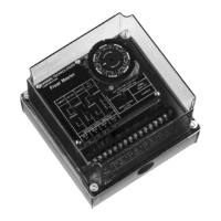
Wiring diagram specific to the Frost Master® Plus controller.
Purpose and application of the soft gas valve for pressure management.
Function and sizing considerations for the equalize valve.
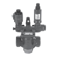
Illustrates a control valve scheme for bottom feed evaporators.
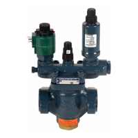
Illustrates a control valve scheme for top feed evaporators.
Guide to selecting appropriate valve sizes based on refrigerant and capacity.
The Hansen Frost Master® is a user-friendly defrost controller designed for efficient removal of frost accumulation on evaporator coil surfaces in industrial and large commercial refrigeration systems. It utilizes reliable solid-state electronics and a precision quartz time clock with time-adjusting slide knobs to sequentially operate through logical defrost steps, ensuring smooth, complete, and effective defrosting. Typically, one controller is used per defrost control valve group.
The Frost Master® sequences solenoid valves and relays to provide quick and efficient defrosting. The defrost process begins with the PUMPOUT step (0-15 minutes), which removes liquid refrigerant from the evaporator, reducing the load from cold residual liquid and exposing more internal surface area to hot gas. This also minimizes the amount of liquid accommodated by the system during defrost.
Next, the HOT GAS step (0-45 minutes) introduces hot gas (or another frost-melting medium) to the evaporator. The duration of this step depends on factors like evaporator design, frost accumulation, hot gas supply quality and quantity, and valve size. It is crucial for the HOT GAS step to be long enough to completely remove all frost; partial removal can lead to increased frost/ice problems over time. A 5-second delay is incorporated before the "H" relay switches to its position, allowing the suction solenoid valve to close before the hot gas solenoid valve opens.
The EQUALIZE step (0-5 minutes) follows, gradually reducing the pressure inside the newly defrosted evaporator to near suction pressure. This is achieved by either a bleed-down solenoid valve bypassing the suction shut-off valve or by allowing the surrounding ambient temperature to cool the evaporator. This step minimizes sudden surges in suction pressure and reduces the impact of pressure changes on the suction accumulator, preventing unnecessary loading/unloading of compressors and pump cavitation.
Finally, the FAN DELAY step (0-5 minutes) resumes normal refrigeration but delays evaporator fan operation for the set time. This allows remaining water droplets from melted frost to freeze onto the evaporator surface, preventing them from being blown into the refrigerated space when air circulation resumes. Usage of all steps is optional and any step can be skipped by setting its time adjustment to zero.
The Frost Master® Plus models offer additional features, including a fifth defrost step called SOFT GAS (0-5 minutes) and a built-in adjustable Temperature Terminate feature. The SOFT GAS step gradually increases pressure inside the evaporator by opening a small soft gas solenoid valve prior to the main hot gas valve, priming the evaporator for full hot gas flow and minimizing pressure shock. The soft gas solenoid valve remains open throughout the SOFT GAS and HOT GAS steps.
| Brand | Hansen |
|---|---|
| Model | FROST MASTER PLUS |
| Category | Controller |
| Language | English |