2
K109i
AUG 2015
** This factor is not suitable when combustible materials
are within 20 feet (6.1 m) of the pressure vessel; refer to
relevant codes for corrected sizing method.
Example: To determine the minimum required capacity
of a relief valve for a vessel containing ammonia that
measures 16 feet in length and 6 feet in outside diameter,
the equation would be as follows: 0.5 x 6 x 16 = 48 lb/min.
Step 2: Determine the pressure setting needed. This
should be at or below the design pressure of the vessel.
The relief setting should also be at least 25% above the
maximum expected operating pressure to avoid “weeping”
of relief valves. The setting may be below (never above) the
design pressure of the vessel, but it is sometimes best to
match vessel design pressure and relief setting to minimize
the likelihood of a discharge.
Step 3: Refer to the Valve Capacity Ratings below and
select the valve with the required capacity (C) at the desired
pressure setting.
VALVE SIZING AND SELECTION
Step 1: Use the formula below, per ANSI/ASHRAE 15
Safety Standard for Refrigeration Systems to calculate the
minimum required discharge capacity in pounds of air per
minute. When selecting a dual pressure-relief valve system,
be aware that each individual valve must have sufficient
capacity to protect the vessel.
C=fDL
C = minimum required discharge capacity of
the relief device in pounds of air per minute.
f = factor for ammonia refrigerant is 0.5**,
factor for R-22 and R-134a refrigerants is 1.6**, for
other refrigerants see ANSI/ASHRAE 15 or contact
factory.
D = outside diameter of vessel in feet.
L = length of vessel in feet.
ONTAC
RIA
YTICAPAC
)gisp(SGNITTESERUSSERPDRADNATS
051 571 002 522 052 572 003 523 053 004
R0065H
R2065H
nim/bl 5.01 2.21 8.31 4.51 0.71 6.81 2.02 8.12 5.32 7.62
mfcs 041 261 381 502 622 842 962 092 213 553
R2365H
nim/bl 22 52 92 23 63 93 24 64 94 65
mfcs 292 733 283 724 274 715 165 606 156 147
R3365H
nim/bl 82 33 73 14 64 05 45 95 36 27
mfcs 773 534 294 055 806 566 327 187 938 459
R4365H
nim/bl 43 93 44 94 45 06 56 07 57 58
mfcs 944 815 685 556 427 397 168 039 999 6311
A0065H
nim/bl 3.13 1.63 9.04 7.54 5.05 3
.55 1.06 9.46 7.96 3.97
mfcs 714 084 445 806 276 637 997 368 729 5501
1065H
2065H
nim/bl 8.53 3.14 8.64 2.25 7.75 2.36 6.86 1.47 6.97
mfcs 674 945 226 596 867 148 319 689 9501
3165H
nim/bl 0.35 1.16 2.96 3.77 4.58 5.39 6.101 7.901 8.711 431
mfcs 407 218 029 8201 6311 3421 1531 9541 7651 2871
4065H
nim/bl 0.27 0.38 0.49 1.501 1.611 1.721 1.831 1.941 2.061 281
mfcs 859 4011 1521 7931 4451 1961 7381 4891 0312 3242
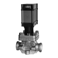
Important Note: These are atmospheric relief valves. Settings equal pressure above atmosphere when outlet is connected via
proper piping to the atmosphere (outside). (scfm = Standard Cubic Feet per Minute)
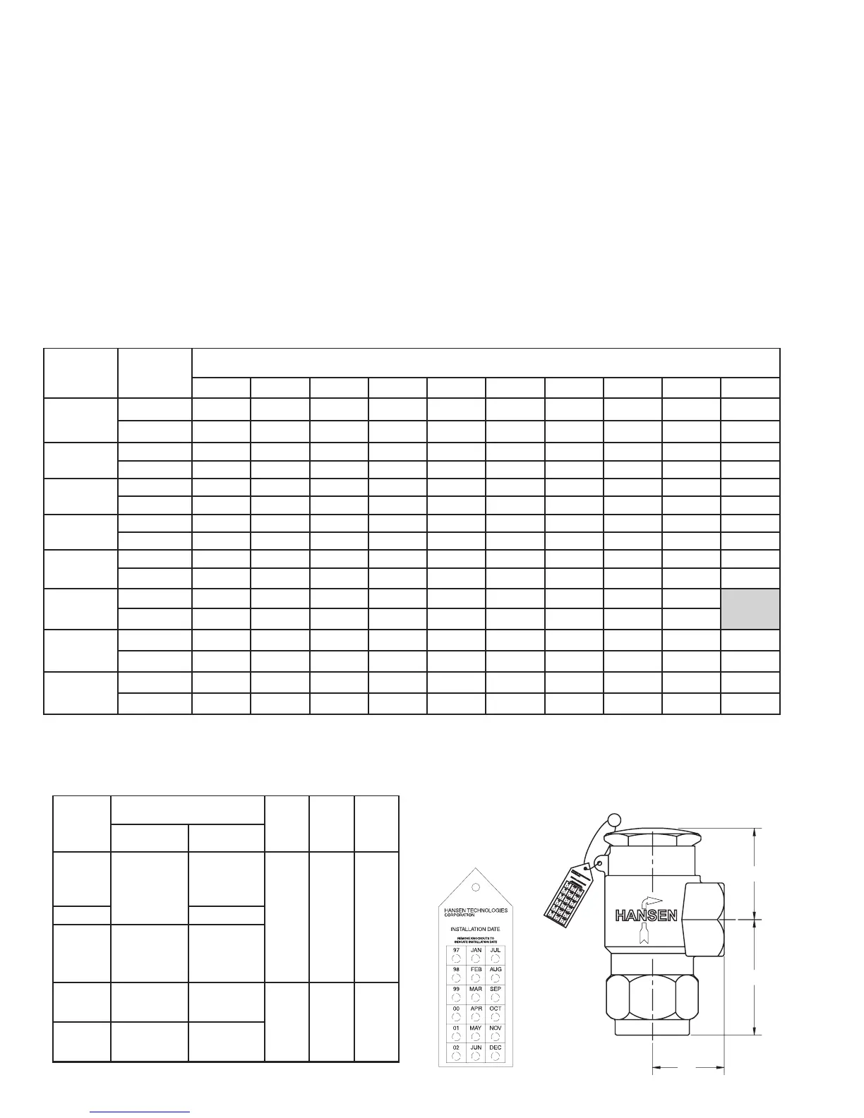
INSTALLATION DIMENSIONS
ONTAC
SNOITCENNOCDEDAERHT
TPN
A
(MM)
B
(MM)
C
(MM)
MOTTOB
T (DN)ELNI
EDIS
T (DN)ELTUO
A0065H
R0065H
1
/
2
T (15)PF"
3
/
4
T (20)PF"
2.13"
(54)
2.75"
(70)
1.63"
(41)
3.00"
(76)
4.13"
(105)
2.25"
(57)
1065H PT (25)F"1
2065H
R2065H
R2365H
3
/
4
T (20)PF" PT (25)F"1
1
3165H
R3365H
T (25)PF"1
1
/
4
T (32)PF"
1
1
/
2
T (40)PF"
4065H
R4365H
1
1
/
4
T (32)PF"
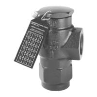
H5600 “R” Series capacity valves have green installation
date tags, while all others are blue.
A
B
C
PRESSURE-RELIEF VALVE CAPACITY RATINGS (NATIONAL BOARD CERTIFIED)
 Loading...