EasyManua.ls Logo

Hansen MCV User Manual

Hansen MCV
44 pages
To Next Page IconTo Next Page
Page #1 background imageLoading...
Page #1 background image
Specifications, Applications,
Service Instructions & Parts
MOTORIZED CONTROL
VALVE
&
CONTROLLERS
Bulletin R649c
September 2018
Port size 1/16” thru 4”
2mm thru 100mm
Motor Operated Valve
Model MCV
INTRODUCTION
The Hansen Motorized Control Valve is a truly unique
motor operated valve which eliminates the most common
concern of other motor operated valves—valve stem
seal leakage. The Motorized Control Valve has no valve
stem seal because the non-electric rotor is enclosed in a
stainless steel cartridge which contains the fluid pressure.
APPLICATIONS
Liquid Make-up to Accumulator
Liquid Injection to Compressors
DX Evaporators
Temperature or Pressure Control
Low or High Side Level Control
Slow Opening and Closing: Suction Stop Valve
No Pressure Drop: Gravity Drain
Modulating or Slow Open/Close Solenoid Operation
ADDITIONAL FEATURES
• Self Calibrating
Relay, current, or voltage input for direct
connection to plant PLC or computer.
All moving parts are sealed so that
frost will not affect operation.
Tight closing Teflon seat.
Canned rotor eliminates valve stem seal leakage.
Controlled opening and closing minimizes
liquid velocity shock, “liquid hammer.
Valve is more compact and light weight
than other motor operated valves.
Same flanges and spacing as Hansen HA4A/
HS4A pressure regulators and solenoid valves.
Suitable for use with ammonia, R22, R134a,
CO2 (up to 800 psi welded) glycol, water,
brines, and other approved refrigerants.
Available with optional Power-Backup feature.
Valve position indicator display included.
Available with weld-in connections.
KEY FEATURES
TABLE OF CONTENTS
Introduction ..............................................................................1
Specifications/Applications ...................................................2-5
Recommended Piping ............................................................6-7
Capacity Tables ...................................................................8-16
Installation Drawings ......................................................... 17-21
Wiring (customer supplied controller) ............................................22-24
HUPS Power Backup System .............................................25-26
Hansen Controllers/Wiring .................................................27-37
Installation Parameter Sheet ................................................... 38
Valve Operation ..................................................................39-40
Service and Maintenance ................................................... 41-42
Valve Parts List .......................................................................43
Ordering Information ............................................................... 44
DIRECT ACTUATION
ELECTRONICS PROVIDE
STRONG, SLOW OPERATION
WITH MINIMAL POWER
CONSUMPTION
PRECISE LINEAR
FLOW REGULATION
OF V-PORT
WATER-TIGHT
NEMA 6 (IP67)
HOUSING
ALL VALVES AVAILABLE WITH ACT SOLUTION

Table of Contents

Question and Answer IconNeed help?

Do you have a question about the Hansen MCV and is the answer not in the manual?

Hansen MCV Specifications

General IconGeneral
BrandHansen
ModelMCV
CategoryControl Unit
LanguageEnglish

Summary

INTRODUCTION

Model MCV

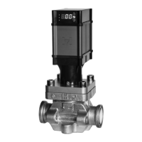
Identifies the specific valve model discussed.

APPLICATIONS

Common Applications

Lists various uses like level control, pressure control, and drain functions.

KEY FEATURES

Valve Design & Performance

Highlights features like watertight housing, slow operation, and linear flow.

MATERIAL SPECIFICATIONS

Mechanical & Electrical Details

Covers pressure ratings, temperature limits, and electrical inputs.

ADVANTAGES

Key Benefits of MCV

Notes low pressure drop, no stem heaters, and reduced water hammer.

VALVE SIZING & POWER BACKUP

Sizing Guidance & Backup Feature

Importance of sizing and optional power backup system.

TYPICAL APPLICATIONS

MCV Control Diagrams

Illustrates MCV use in liquid makeup and temp/pressure control.

TYPICAL APPLICATIONS

MCV/MCXV Application Diagrams

Shows chiller and compressor liquid injection applications.

TYPICAL APPLICATIONS

MCV for Suction Stop & Drain

Illustrates MCV for slow opening/closing and gravity drain.

RECOMMENDED PIPING PRACTICES

Liquid Feed Piping Configuration

Shows recommended piping for liquid feed between vessels.

RECOMMENDED PIPING PRACTICES

Inlet Piping Best Practices

Illustrates recommended vs. not recommended inlet piping.

MOTORIZED CONTROL VALVE CAPACITIES

Ammonia Suction Vapor Capacities

Tables for Ammonia suction vapor capacity in Tons and kW.

MOTORIZED CONTROL VALVE CAPACITIES

R-22 Suction Vapor Capacities

Tables for R-22 suction vapor capacity in Tons and kW.

MOTORIZED CONTROL VALVE CAPACITIES

R-134a Suction Vapor Capacities

Tables for R-134a suction vapor capacity in Tons and kW.

MOTORIZED CONTROL VALVE CAPACITIES

R-404 Suction Vapor Capacities

Tables for R-404 suction vapor capacity in Tons and kW.

MOTORIZED CONTROL VALVE CAPACITIES

R-507 Suction Vapor Capacities

Tables for R-507 suction vapor capacity in Tons and kW.

MOTORIZED CONTROL VALVE CAPACITIES

Liquid Make-Up & DX Capacities

Tables for MCR/MCXV liquid make-up/DX in Tons and kW.

MOTORIZED CONTROL VALVE CAPACITIES

High Pressure Liquid Line Capacities

Tables for Ammonia & R-22 high pressure liquid in Tons and kW.

MOTORIZED CONTROL VALVE CAPACITIES

High Pressure Liquid Line Capacities (Cont.)

Tables for R-134a, R-404, R-507 high pressure liquid in Tons/kW.

MOTORIZED CONTROL VALVE CAPACITIES

Hot Gas Solenoid Defrost Capacities

Table for MCR/MCV hot gas defrost capacities.

MOTORIZED CONTROL VALVE INSTALLATION DRAWINGS

MCXV & 3/4"-1-1/4" Valve Dimensions

Installation drawings for MCXV and smaller MCV/MCR valves.

MOTORIZED CONTROL VALVE INSTALLATION DRAWINGS

1-1/2"-2" & 3" Valve Dimensions

Installation drawings for 1-1/2"-2" and 3" MCV/MCR valves.

MOTORIZED CONTROL VALVE INSTALLATION DRAWINGS

4" Valve Dimensions

Installation drawings for 4" MCV/MCR valves.

INSTALLATION OVERVIEW & MANUAL CONTROL

Installation Best Practices

General guidelines for valve installation and handling.

Manual Control Tool (MCT) Usage

Instructions for operating the Manual Control Tool.

INSTALLATION INSTRUCTIONS

Valve Installation & Conversion

Steps for new valve installation and SMV to MCV conversion.

CUSTOMER POWER SUPPLY & CONTROLLER WIRING

Modulating Control Wiring

Diagram for connecting customer power/controller for modulating control.

MOTORIZED CONTROL VALVE POWER BACKUP SYSTEM

HUPS System Overview & Indicators

Details on the Uninterruptable Power Supply and its indicators.

MOTORIZED CONTROL VALVE POWER BACKUP SYSTEM

Power Backup System Wiring

Wiring diagram for the power backup system.

HANSEN CONTROLLERS OVERVIEW

PXVC Controller Specifications

Technical specifications for the PXVC controller series.

HANSEN CONTROLLERS - PXVC-PT

PXVC-PT Control Overview & Operation

Overview of PXVC-PT for superheat/subcooling control.

HANSEN CONTROLLERS - PXVC-PT

PXVC-PT Inputs & Outputs

Diagram and description of PXVC-PT terminal connections.

HANSEN CONTROLLERS - PXVC-PT

PXVC-PT Wiring Diagram (115V/230V)

Wiring diagram for the PXVC-PT controller.

HANSEN CONTROLLERS - FUNCTIONAL DESCRIPTIONS

PXVC Controller Applications & Selections

Descriptions of PXVC-T, -L, -DX, -P and sensor/valve selection.

HANSEN CONTROLLERS - USER INTERFACE

PXVC Display & Keypad Operation

Guide to operating the PXVC controller's display and keypad.

HANSEN CONTROLLERS - INPUT/OUTPUT CONFIGURATIONS

PXVC I/O Terminal Descriptions

Terminal descriptions for PXVC-T, -L, -P, -DX controllers.

HANSEN CONTROLLERS - WIRING DIAGRAMS

PXVC-T (Temperature) Wiring

Wiring diagram for the PXVC-T temperature controller.

HANSEN CONTROLLERS - WIRING DIAGRAMS

PXVC-L (Liquid Level) Wiring

Wiring diagram for the PXVC-L liquid level controller.

HANSEN CONTROLLERS - WIRING DIAGRAMS

PXVC-P (Pressure) Wiring

Wiring diagram for the PXVC-P pressure controller.

HANSEN CONTROLLERS - WIRING DIAGRAMS

PXVC-DX (Superheat) Wiring

Wiring diagram for the PXVC-DX superheat controller.

INSTALLATION PARAMETERS RECORD

Valve & Application Data Entry

Fields to record valve description, installation, and application data.

MOTORIZED CONTROL VALVE OPERATION

Core Operation & Electrical Basics

Explains valve drive, modes, and electrical connections.

MOTORIZED CONTROL VALVE OPERATION

User Interface & Menu Navigation

Guide to operating the valve's user interface menu and parameters.

SERVICE AND MAINTENANCE

MCV Service & Disassembly/Assembly

Procedures for servicing, disassembling, and reassembling the MCV.

SERVICE AND MAINTENANCE

MCXV Service & Disassembly/Assembly

Procedures for servicing, disassembling, and reassembling the MCXV.

MOTORIZED CONTROL VALVE PARTS LIST

MCXV, MCV, MCR Parts Identification

Lists parts and P/N for MCXV, MCV, MCR valve types.

ORDERING INFORMATION & OPTIONS

Valve Ordering & Optional Components

Details on ordering valves, controllers, and accessories.

PRODUCT INFORMATION & SAFETY

ACTTM, MVP, Caution & Warranty

Covers ACT protection, MVP platform, safety cautions, and warranty.

Related product manuals