21
R649c
SEPTEMBER 2018
INSTALLATION INSTRUCTIONS
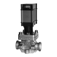
NEW COMPLETE VALVE
NOTE: Do not power on actuator until it is mounted to
the valve and the set screws are properly torqued.
1. Remove valve, actuator, and remaining contents from
box.
2. For flanged valves, align valve with arrow
pointing in direction of flow and mount per install
protocol. For weld in line valves, it is recommended
to remove the cartridge/V-port assembly during
welding by loosening bolts and removing
bonnet. Replace cartridge/V-port assembly after
valve body is installed and ensure o-ring in installed
onto cartridge.
3. Install bonnet onto cartridge assembly and tighten
four bonnet bolts.
4. Place Manual Control Tool (MCT) onto the
top of magnetic cartridge assembly. Continue
to rotate the tool counterclockwise until the
valve is closed and the V-port will no longer move.
5. Grease exterior of cartridge above the O-ring
with supplied low temp, high load, low RPM
grease such as Lubriplate Aero or similar.
6. Check the base of the actuator to ensure
that the set screws are not protruding past the
ID of the threaded ring. If necessary back the set
screws out to prevent interference during installation.
7. Install actuator onto cartridge. Press firmly
down on the top of the actuator to
ensure it fully seats. The gap between the base
of the actuator and bonnet should be less than 1/16”.
8. Rotate actuator to orient in desired position
and torque the 3 set screws at base to 4 in-lb using
3/32” hex key.
9. Wire the flying lead ends of the cable to power and
the desired input signal and feedback loop per wiring
diagram.
10. Connect the red and green cables to the actuator
11. Upon power-up, the valve will automatically calibrate.
12. Actuator is programmed for 4-20mA input signal.
See page 40 to change if other signal is used.
CONVERSION FROM SMV TO MCV
NOTE: Do not power on actuator until it is mounted to
the valve and the set screws are torqued.
1. Isolate and pump down existing valve per PSMs.
2. Disconnect existing powerhead connections.
3. Unscrew the powerhead screws and remove the
powerhead.
4. Unscrew bonnet bolts and remove the bonnet.
5. Remove existing can and cartridge assembly. Ensure
old gasket is removed from counter bore on top face
of valve.
6. Remove new actuator and remaining contents from
box.
7. Install new cartridge gasket to counter bore on top
face of valve.
8. Install V-port into cartridge while fully supporting
the V-port and cartridge and carefully aligning the
threaded shaft of cartridge with the low friction nut
of V-port. Carefully thread together 6-8 turns and
align the anti-rotation slot on the V-port with the
anti-rotation pin of the cartridge. Using the MCT,
fully thread the V-port into the cartridge, screwing
the V-port fully into the cartridge by turning the rotor
clockwise.
9. Install new rotor cartridge/V-port assembly into valve.
10. Install new bonnet over cartridge assembly and
tighten bonnet bolts.
11. Ensure O-ring is installed onto cartridge assembly.
12. Place Manual Control Tool (MCT) onto the top of
magnetic cartridge assembly. Continue to rotate
the tool counterclockwise until the valve is closed
and the V-port will no longer move.
13. Grease exterior of cartridge above the O-ring with
supplied low temp, high load, low RPM grease such
as Lubriplate Aero or similar.
14. Check the base of the actuator to ensure that the set
screws are not protruding past the ID of the threaded
ring. If necessary back the set screws out to prevent
interference during installation.
15. Install new actuator onto cartridge. Press firmly down
on the top of the actuator to ensure it fully seats. The
gap between the base of the actuator and bonnet/
cartridge should be less than 1/16”.
16. Rotate actuator to orient in desired position and
torque the 3 set screws at base to 4 in-lb using 3/32”
hex key.
17. For HMMR/HMMV conversion, connect the black
7 pin dongle connector to the existing connection
already wired in place. The VPIF can be left in place
if desired.
NOTE: For HMSV conversion cut off black 7 pin dongle
connector to power and input/output, per wiring
diagram. It is important to remove the 24VAC to the
pink and yellow relay signal wires. Voltage to this
line will cause damage as the input should only be
a closed contact switched to ground.
18. Connect the red and green cables to the actuator.
19. Upon power-up, the valve will automatically calibrate.
20. Confirm actuator is programmed for valve size and
input signal through the keypad display. See page 40.
NOTE: Gaskets and O-rings should be replaced with new
if they are removed from valve. Recommend to lubricate
new gaskets/O-rings with oil prior to installing. Bolts
should have anti-seize applied.
MOTORIZED CONTROL VALVE INSTALLATION