40
R649c
SEPTEMBER 2018
USER INTERFACE MENU AND
INSTRUCTION GUIDE
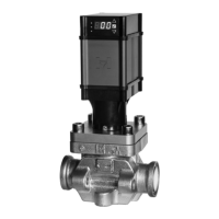
The user interface is a located on the front of the valve
and when in normal operation will display the % open
of the valve V-port. The setup menu can be entered to
automatically calibrate, adjust the control parameters, and
view current settings. All displays in this menu start with
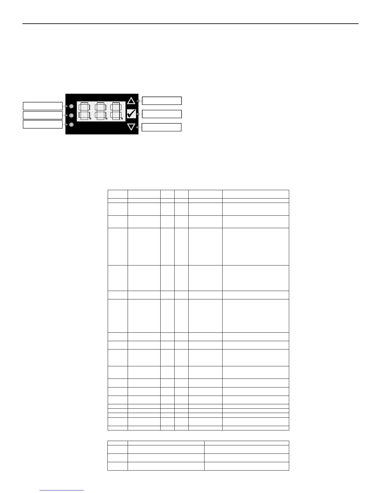
the letter “H.”. The keypad and display are shown below
All LEDs will be on for couple seconds on power-up.
After that the Red and Blue LED should not turn on. The
Green LED indicates valve is in manual mode (H.02).
To enter and navigate the menu, follow the steps below:
1. Press and hold the UP and DOWN arrow buttons on the keypad
for 3 seconds
2. Upon entering, H.01 will be shown on the display.
3. Use the UP and DOWN arrow buttons to navigate through
the list below.
4. To display and/or modify a value for that description, press
the ENTER button.
5. Use the UP and DOWN arrow buttons to change the value.
6. Press the ENTER button to save the value. The display will
return to the setup menu
7. Repeat steps 3-6 for all desired changes.
8. Exit the menu at any time by pressing and holding the ENTER
button on the keypad for 3 seconds.
NOTE: Exiting the menu will NOT save the value to the valve .
NOTE: Valve can stay in Manual Mode (H.02) for an
infinite amount of time.
If E.01 or E.02 become active, the valve will drive to zero
and close until the signal issue has been rectified. Once
the input signal is within the proper limits, the actuator
will return to normal operation.
The Setup Menu
The setup menu is used to automatically calibrate, adjust the control parameters, and view current
settings. All displays in this menu start with the letter “H.”. The keypad and display are shown below:
To enter and navigate the menu, follow the steps below:
1. Press and hold the UP and DOWN arrows on the keypad for 3 seconds
2. Upon entering, H.01 will be shown on the display.
3. Use the UP and DOWN arrows to navigate through the list below.
4. To display and/or modify a value for that description, press the ENTER button.
5. Use the UP and DOWN arrows to change the value.
6. Press the ENTER button to save the value. The display will return to the setup menu.
7. Repeat steps 3-6 for all desired changes.
8. Exit the menu at any time by pressing and holding the ENTER button on the keypad for 3
seconds.
Red LED
Green LED
Blue LED
Down Button
Enter Button
Up Button
Setup Parameters
Display
(Menu #)
Mode Description Min
Value
Max
Value
Factory Setting Comments
- Normal Operation 0 100 - Valve % Open
H.01 Re-Zero
Calibration
0 1 0 0 = No Action
1 = Force motor to recalibrate zero
Display will show CAL
H.02 Automated/Manual
Mode
0 100 0 Mode becomes Manual when entered.
Green LED will illuminate.
Range: 0 - 100% when Enter is pressed
H.03 Valve Size 0
9
0
00 = 3/4”
02 = 1”
03 = 1-1/4”
04 = 1-1/2”
05 = 2”
07 = 3”
08 = 4”
09 = 1/16", 7/32", 9/32"
Valve will automatically calibrate
after selection is made by pressing Enter
H.04 Input Signal Type 0
5
0 0 = 4-20mA
1 = 0-20mA
2 = 0-5Vdc
3 = 0-10Vdc
4 = 1-6Vdc
5 = Relay input
H.05 Output Signal Type 0
1
0 0 = 4-20mA
1 = 0-20mA
H.06 Operation Type 0 3 0 0 = Modulating (Direct)
(input signal increase % open increase)
1 = Modulating (Reverse)
(input signal increase % open decrease)
2 = Open/Close (Direct)
(Closed relay fully closed valve)
3 = Open/Close (Reverse)
(Closed relay fully open valve)
H.07 Speed 25 100
50
Motor speed adjustment
Increments of 25%
H.08 Power Backup
Supply Status
0 1 0 0 = Disabled
1 = Enabled
H.09 Power Backup Fail
Safe Position upon
power loss
0
2
0 Define motor position on power loss
0 = close
1 = open
2 = user defined position @ H. 10
H.10 Fail Safe Position
when H.09 = 2
0 100 0 Number between
0 – 100
Increments of 10
H.11 Alarm Log 0 9
A0 = Active alarm
A1 A9 = logged alarm. A9 oldest
H. 12 Max. Open Limit 30 100 100 Max. Open must be greater than Min.
Close increments of 10
H. 13 Min. Close Limit 0 40 0 Min. Close Limit must be less than Max.
Open Limit in increments of 10
H. 14 Input Dampening 1 5
H. 20 Password protected 0 999
H. 21 Measuring interval 1 50
H. 34 Factory Reset
Input value of 1 will reset all parameters to
factory defaults
H. 99 Software Version
Displays Software Version
Error Codes with Explanations
Error # Description Notes
E.01 Input signal present on the 4-20mA Control Input
greater than expected.
The 4-20mA signal present on the Control Input is
greater than 22mA
E.02 Input signal present on the 4-20mA Control Input
less than expected.
The 4-20mA signal present on the Control Input is less
than 3mA
PF Power Failure when the incoming voltage is less
than expected.
The incoming voltage is less than 19V.
TABLE 27
MOTORIZED CONTROL VALVE OPERATION