2
R649c
SEPTEMBER 2018
MATERIAL SPECIFICATIONS
Mechanical
Maximum Safe Working Pressure:
400 psig (28 bar) flanged, 800 psig (55 bar) welded
Maximum Opening Pressure Differential:
400 psig (28 bar) flanged, 800 psi (55 bar) all sizes
Ambient Operating Temperature:
-40˚F to 122˚F (-40˚C to 50˚C)
Refrigerant Operating Temperature:
-75˚F to 240˚F (-60˚C to 115˚C)
IP67 Rating (NEMA 6)
Electrical:
Supply Voltage: 24VAC or 24VDC via NEC Class 2 Source
Power Draw: 20W per valve
Input Control Signal Types: 4-20mA, 0-20mA, 0-5VDC,
0-10VDC, 1-6VDC, relay closed contact
Output Feedback Signal Types: 0-20mA, 4-20mA
Material Specifications
Body: Ductile iron, ASTM A536
Bonnet Plate: Steel, zinc plated with yellow chromate
V-port Seal: Teflon
Cartridge Assembly: Stainless Steel
Cartridge O-ring: Neoprene
Actuator Housing: Aluminum
Corrosion Protection: Zinc plating is standard on
bodies up to 1-1/4”, ACT™ available on all valves
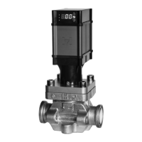
APPLICATIONS
The Hansen Motorized Control Valve is ideal for applications
where external leakage is intolerable. The valve is suitable
for use with a variety of fluids, including those that are
incompatible with copper, such as ammonia, because the
motor is isolated from the refrigerant. Typical uses include
slow opening solenoid valve, temperature controlled
evaporator regulator, liquid injection to screw compressors,
pressure control, liquid level control of pump accumulators,
high side receivers or low side flooded chillers, or as a
gravity drain valve.
The full ported MCV valve series is for computer controlled
operations using 4-20 mA signals. The MCV is ideal for
precise temperature and pressure control, hot gas defrost,
and other applications where accurate process control is
required. The MCV valves series is also for applications
requiring open/close operation only.
The MCR valve with expansion plug is for high pressure
drop applications such as liquid makeup and liquid
injection. The MCR valve series is also suitable for suction
line, liquid line and hot gas line where reduced capacities
more closely match the expected operating conditions.
The MCXV valve series is best suited for liquid injection
of screw compressors and direct expansion evaporators.
Refer to pages 3-5 for typical applications.
ADVANTAGES
The Motorized Control Valve can be used for applications
which require a very low pressure drop (e.g. suction lines),
or no pressure drop (e.g. equalizing or drain lines). No
pressure drop is required to operate, unlike most pressure
regulators and solenoid valves which require a minimum
2 psi pressure drop to keep the valve fully open.
Motorized Control Valves are drop-in replacement for
Hansen and other select solenoid and pressure regulating
valves.
The Motorized Control Valve does not require stem shaft
heaters like other open motorized valves.
The Motorized Control Valve is slow opening and closing
(ranging from 13 to 45 seconds) depending on valve size
and speed settings which minimizes the potential for liquid
velocity shock or “water hammer” often experienced with
quick opening and closing solenoid valves.
POWER BACKUP FEATURE
The Motorized Control Valve is available with an optional
power backup system that will control the valve to a user
defined location upon a loss of the incoming voltage. This
system can be used in place of an upstream solenoid to the
valve. Refer to pages 25 – 26 for details and wiring.
VALVE SIZING
Proper valve sizing is important for smooth operation and
long, trouble-free life of the valve. Therefore, capacity
at both the maximum and minimum flow and pressure
drop should be analyzed. Pressure drop across the valve
dramatically increases the capacity of the valve. A valve with
8 psi pressure drop has twice the capacity of a valve with a
2 psi pressure drop. Ideally, valves should operate between
15% and 85% open for optimum trouble-free control. Refer
to the capacity tables on pages 8–16 or the Hansen sizing
program found at www.hantech.com.
LIQUID MAKE-UP APPLICATIONS
For applications with a large pressure drop across
the Motorized Control Valve, attention must be paid to
proper outlet line sizing to accommodate flash gas. It is
recommended that dual Motorized Control Valves in parallel
be used when the low load (weekend load) is less than 15%
of the properly sized full load capacity for the application.
Also, for applications requiring a valve size over 2˝ port size,
it is strongly recommended that two liquid make-up valves
in parallel be used. This valve arrangement could be two
Motorized Control Valves or one solenoid valve with hand
expansion valve and one Motorized Control Valve to be used
as a “trim” valve under low load conditions.
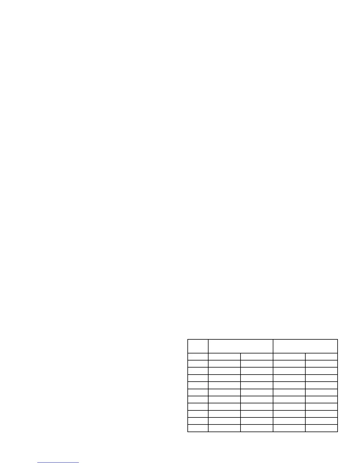
LIQUID LINE SIZING
Liquid lines should be adequately sized for the capacity
of the valve. Listed below are the IIAR recommended
capacities for liquid lines. R22 capacities based on 3 ft/s
liquid velocity. For R134a, use 94% of R22 capacity; R404
80%; R507 60%.
TABLE 1
LINE
SIZE
MAXIMUM CAPACITY
AMMONIA
MAXIMUM CAPACITY
R22
1/2˝ 32 Tons 112 kW 8 Tons 27 kW
3/4˝ 58 Tons 208 kW 14 Tons 49 kW
1˝ 97 Tons 340 kW 24 Tons 82 kW
1-1/4˝ 179 Tons 625 kW 42 Tons 147 kW
1-1/2˝ 254 Tons 890 kW 58 Tons 202 kW
2˝ 496 Tons 1740 kW 110 Tons 384 kW
2-1/2 ˝ 729 Tons 2550 kW 155 Tons 543 kW
3˝ 1160 Tons 4060 kW 241 Tons 845 kW
4˝ 2040 Tons 7140 kW 416 Tons 1457 kW
5˝ 3300 Tons 11606 kW 654 Tons 2289 kW
6˝ 4890 Tons 17198 kW 946 Tons 3309 kW
NH3 capacities are based on IIAR Refrigeration Piping
Handbook tables.