41
R649c
SEPTEMBER 2018
SERVICE AND MAINTENANCE
MCV DISASSEMBLY
1. Isolate the valve from the refrigerant pressure and
evacuate the refrigerant.
NOTE: Always use caution when removing the actuator
and entering the valve cavity.
2. Disconnect the red and green cables from the actuator.
3. Remove the actuator by loosening but not removing
the set screws.
4. To enter the valve cavity, carefully loosen and remove
the larger bonnet bolts and then the bonnet.
5. Grasp the top of the cartridge and while lifting out
squarely, remove the cartridge assembly, taking
care not to bend the shaft. If cartridge removal is
difficult, remove by placing the MCT on the cartridge
and rotating counterclockwise and the cartridge will
press out. WARNING: Don’t bend shaft.
6. Remove the V-port from the cartridge assembly by
unscrewing the rotor counterclockwise.
MCV ASSEMBLY
1. Install new cartridge gasket to counter bore on top
face of valve.
2. Ensure V-port is installed into new rotor cartridge.
To install V-port into cartridge fully supporting the
V-port and cartridge while carefully aligning the
threaded shaft of cartridge with the low friction nut
of V-port. Carefully thread together 6-8 turns, and
align the anti-rotation slot on the V-port with the
anti-rotation pin of the cartridge. Fully thread the
V-port into the cartridge, screwing the V-port fully
into the cartridge by turning the rotor clockwise.
3. Install new rotor cartridge/V-port assembly into valve.
4. Install new bonnet over cartridge assembly and
torque bolts to 35 ft-lbs.
5. Install O-ring onto cartridge.
6. Place Manual Control Tool (MCT) onto the top of
magnetic cartridge assembly. Continue to rotate
the tool counterclockwise until the valve is closed
and the V-port will no longer move.
7. Grease exterior of cartridge above the O-ring with
supplied low temp, high load, low RPM grease such
as Mobilith SHC PM 460 or similar.
8. Check the base of the actuator to ensure that the set
screws are not protruding past the ID of the threaded
ring. If necessary back the set screws out to prevent
interference during installation.
9. Install new actuator onto cartridge. Press firmly down
on the top of the actuator to ensure it fully seats. The
gap between the base of the actuator and bonnet
should be less than 1/16”.
10. Rotate actuator to orient in desire position and torque
the 3 set screws at base to 4 in-lb using 3/32” hex
key.
11. Connect the red and green cables to the actuator.
12. Upon power-up, the valve will automatically calibrate.
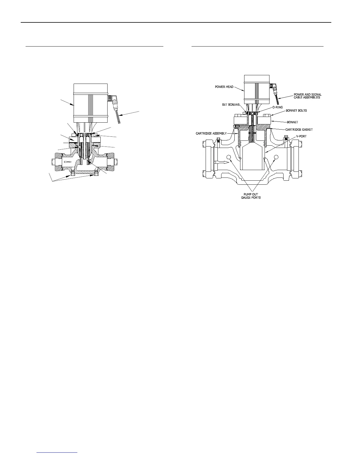
POWER AND SIGNAL
CABLE ASSEMBLIES
O-RING
BONNET BOLTS
BONNET
GUIDE PIN
CARTRIDGE GASKET
V-PORT
PUMP OUT
GAUGE PORTS
ACTUATOR
SET SCREWS
CARTRIDGE ASSEMBLY
FIGURE 31
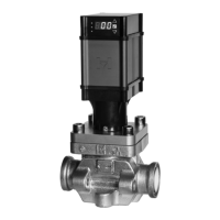
3/4” THRU 2” MOTORIZED CONTROL VALVE 3” THRU 4” MOTORIZED CONTROL VALVE
FIGURE 32