42
R649c
SEPTEMBER 2018
MCXV DISASSEMBLY
1. Isolate the valve from the refrigerant pressure and
evacuate the refrigerant.
NOTE: Always use caution when removing the cartridge
and entering the valve cavity.
2. Disconnect the red and green cables from the actuator.
3. Loosen but do not remove the set screws and lift the
actuator off the cartridge.
4. To enter the valve capacity, carefully loosen and
remove the larger bonnet bolts from bottom of valve
and then the bonnet.
5. Grasp the top of the cartridge and remove the
cartridge assembly by lifting it out squarely taking
care not to bend the shaft. If the cartridge removal
is difficult, remove it by placing the MCT on the
cartridge and rotating counterclockwise and the
cartridge will press out. CAUTION: Do not bend shaft.
6. Using a 7/16 inch socket or wrench remove the seat
(P/N 75-3118) and washer (P/N 75-3119)
7. Rotate needle clockwise and remove. This is the lowest
level disassembly intended for the operator to complete
MCXV ASSEMBLY
1. Install new seat washer (P/N 75-3119) onto seat (P/N
75-3118) and apply refrigerant suitable thread locker
to seat threads
2. Install assembled seat into body and torque to 5
ft.-lbs.
3. Thread modulating needle into cartridge assembly
counterclockwise (This is a left hand thread).
4. Using MCT, rotate the magnet while threading the
modulating needle into the cartridge and ensure the
needle engages the drive mechanism.
NOTE: If the needle bottoms out (protrudes more than ½”),
the needle is not engaged into the drive mechanism.
If this happens loosen the needle slightly and rotate
the magnet a fraction of a turn until the needle is
able to be properly threaded into the cartridge.
5. Lubricate gasket with refrigeration oil and install
onto the body ensuring it lies concentric with the
raised surface
6. Install cartridge assembly onto body
7. Install O-ring onto cartridge
8. Place MCT onto the top of the cartridge assembly
and rotate counterclockwise until the valve is closed
and the V-port will no longer move.
9. Grease exterior of cartridge above O-ring with
supplied low temp, high load, low RPM grease such
as Mobilith SHC PM 460 or similar.
10. Check the base of the actuator to ensure the set
screws are not protruding past the I.D. of the threaded
ring. If necessary, back the set screws out to prevent
interference during installation.
11. Install new actuator onto cartridge. Press down firmly
on the top of the actuator to ensure it fully seats. The
gap between the base of the actuator and bonnet/
cartridge should be less than 1/16”.
12. Rotate actuator to orient display in desired position
and torque the 3 set screws at base to 4 in-lb using
3/32” hex key.
13. Connect the red and green cables to the actuator.
14. Upon power-up the valve will automatically calibrate.
SERVICE AND MAINTENANCE
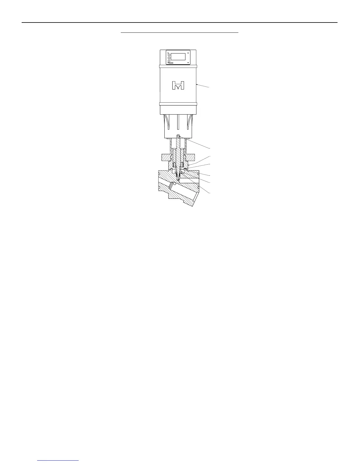
MCXV MOTORIZED CONTROL VALVE
FIGURE 33
6HDW
6HDW:DVKHU
*DVNHW
&DUWULGJH$VVHPEO\
6HW6FUHZV
$FWXDWRU
&DEOHVFRQQHFW
WRRSSRVLWHVLGH
RIDFWXDWRUQRW
VKRZQ
1HHGOH
Needle/V-port
AssemblyKit
(includesgasketkit)
Cartridge
AssemblyKit
(gasketkit,cartridge,
grease)
SMVtoMCV
ConversionKit**
(Actuator,DongleCable,
Bonnet,Bolts,Cartridge
Gasket,BonnetO-ring,
Grease)
SMVPowerCloseto
MCVPowerBackup
ConversionKit**
75-1347*** 75-1347withHUPS***
75-1348*** 75-1348withHUPS***
75-1347*** 75-1347withHUPS***
75-1348*** 75-1348withHUPS***
NOTE:GasketsandO-ringsshouldbereplacedwithnewiftheyareremovedfromvalve.Recommendtolubricatenewgaskets/O-ringswithoilpriortoinstalling.Bolts
shouldhaveanW-seizeapplied.
* Includesstrainer
**All SMV to MCV conversion kits REQUIRE MCT to be available for conversion
*** All 3” and 4” SMV to MCV conversion kits REQUIRE a V-port kit to be requested separately