25
R649c
SEPTEMBER 2018
HUPS POWER BACKUP SYSTEM
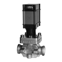
The Motorized Control Valve can be wired to an optional
power backup system that will control the valve to a user
defined location upon a loss of the incoming voltage.
These locations of fully open, fully closed, or another
open position can all be programmed through the user
interface display. During power loss feedback signal will
not be available and input signal to valve will not be utilized.
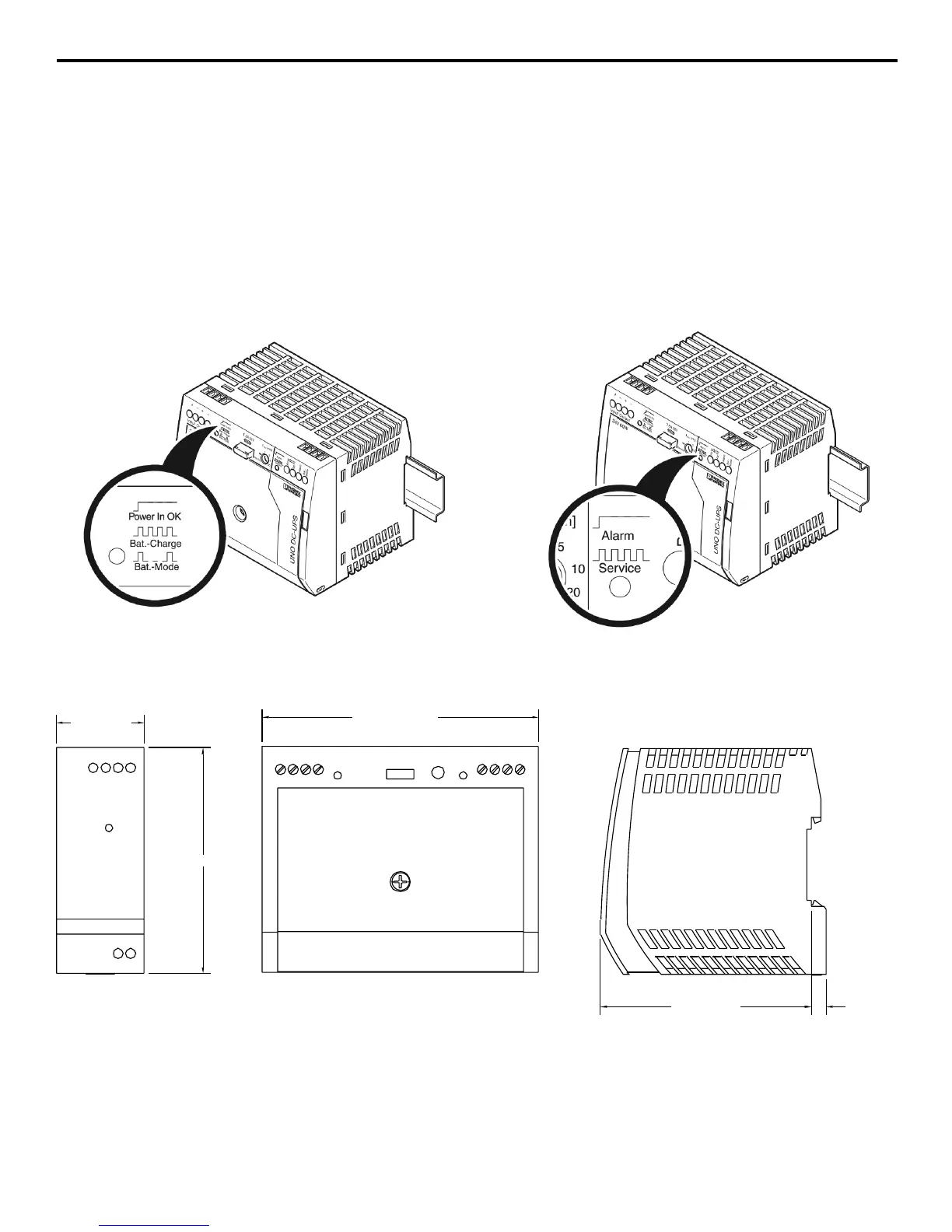
The Uninterruptable Power Supply (HUPS) consists of a
voltage monitoring system as well as an integrated battery.
The optional HUPS when combined with an appropriately
sized DC power supply can run up to three Motorized
Control Valves. If the incoming line voltage drops below
19 volts and the power backup system is active, the
system will switch over to use the battery power. This
UPS mode is indicated by a slow flashing green LED as
seen on the diagram below. The RED will illuminate when
there is an issue or the battery needs to be replaced.
Once the incoming voltage level is restored, the valve will
automatically return to normal control mode.
MOTORIZED CONTROL VALVE POWER BACKUP SYSTEM
A
dd in (Voltage Modulating, Current Modulating, Slow/Open Close) wiring diagrams after this section.
The Motorized Control Valve can be wired to an optional power backup system that will control the valve to a user
defined location upon a loss of the incoming voltage. These locations of fully open, fully closed, or another open
position can all be programmed through the user interface display. The Uninterruptable Power Supply (UPS) consists
of a voltage monitoring system as well as an integrated battery. The optional UPS when combined with an
appropriately sized DC power supply can run up to 3 Motorized Control Valves. If the incoming line voltage drops
below 19 volts and the power backup system is active, the system will switch over to use the battery power. This
UPS mode is indicated by a slow flashing green LED as seen on the diagram below. The RED illuminate when there is
an issue or the battery needs to be replaced. Once the incoming voltage level is restored, the valve will
automatically return to normal control mode.
HUPS LED Mode Indicator – Green LED
HUPS LED Alarm Indicator – Red LED
(+) 0/4-20mA Input Signal
(+) 0-5/10VDC & Relay Input
Signal
FIGURE 18
1.38 (35mm)
3.54 (90mm)
3.30 (84mm)
.69 (18mm)
1.76 (45mm)
3.54 (90mm)
.24 (6mm)
1.76 (45mm)
.69 (18mm)
.24 (6mm)
3.54 (90mm)
3.54 (90mm)
4.33 (110mm)
1.38 (35mm)
3.54 (90mm)
3.30 (84mm)
.69 (18mm)
1.76 (45mm)
3.54 (90mm)
.24 (6mm)
1.76 (45mm)
.69 (18mm)
.24 (6mm)
3.54 (90mm)
3.54 (90mm)
4.33 (110mm)
3.30 (84mm)
.24 (6mm)
1.76 (45mm)
.69 (18mm)
.24 (6mm)
3.54 (90mm)
3.54 (90mm)
4.33 (110mm)