39
R649c
SEPTEMBER 2018
OPERATION
The valve is driven by a motor and electronics that are
placed inside of an IP67 watertight rated housing. Upon
receiving an input signal, the motor shaft rotates and
transfers the force via a magnetic coupling to a threaded
stem. This cartridge stem directly drives the valve
V-port to open or closed based on the incoming signal.
The actuator can run on incoming voltage of either 24VAC
or 24VDC. This is provided via two wires on the 5 pin
connector. Upon power-up the valve will run through a
self-calibration process. The actuator can be configured
into 1 of 2 operational modes: modulating or slow/
open close based on the wiring of the 8 pin connector
along with the menu selection. There are 2 additional
wires on the 8 pin connector that provide 0/4-20mA
feedback of the valve V-port position. The feedback
does not have to be connected to operate the valve.
To operate in the modulating mode, a milliamp or voltage
input control signal must always be maintained to keep the
V-port in position. A loss of signal or a signal out of range
will drive the valve closed and display an error code. When
the signal is present, the V-port will move and stay at that
location until the input signal changes. If loss of input power
occurs, the valve remains in its current position, unless the
valve is equipped with HUPS (Hansen power backup system).
To operate in the slow open/close solenoid mode, a relay
contact is required as a means of an input signal to fully
open or close the valve. No external voltage is needed
to power the relay signal. As a default, when the relay
is closed the valve is closed. A loss of signal will drive
the valve closed. If loss of input power occurs, the valve
remains in its current position, unless the valve is equipped
with HUPS.
ELECTRICAL INFORMATION & WIRING
The Motorized Control Valve will take either a 24VAC or
24VDC input voltage from an NEC Class 2 source and
either a voltage, current, or relay input control signal. It
is recommended to use a separate power supply from the
main supply for the current and voltage input signal to
maintain signal integrity. A dedicated incoming voltage
supply must be sized properly to deliver the proper amount
of voltage and current to actuator. A transformer rated at
24VA per valve or a power supply rated at .8A per valve
will be sufficient.
The incoming control signal can be wired and configured
as any of the following: 4-20mA, 0-20mA, 0-5VDC, 0-10VDC,
1-6VDC, and a relay closed contact. The output feedback
signal of the valve position can be configured as 4-20mA
or 0-20mA.
ELECTRICAL MAINTENANCE
Check calibration and HUPS function on a routine basis.
Check controller and controller wiring for corrosion and
proper connection.
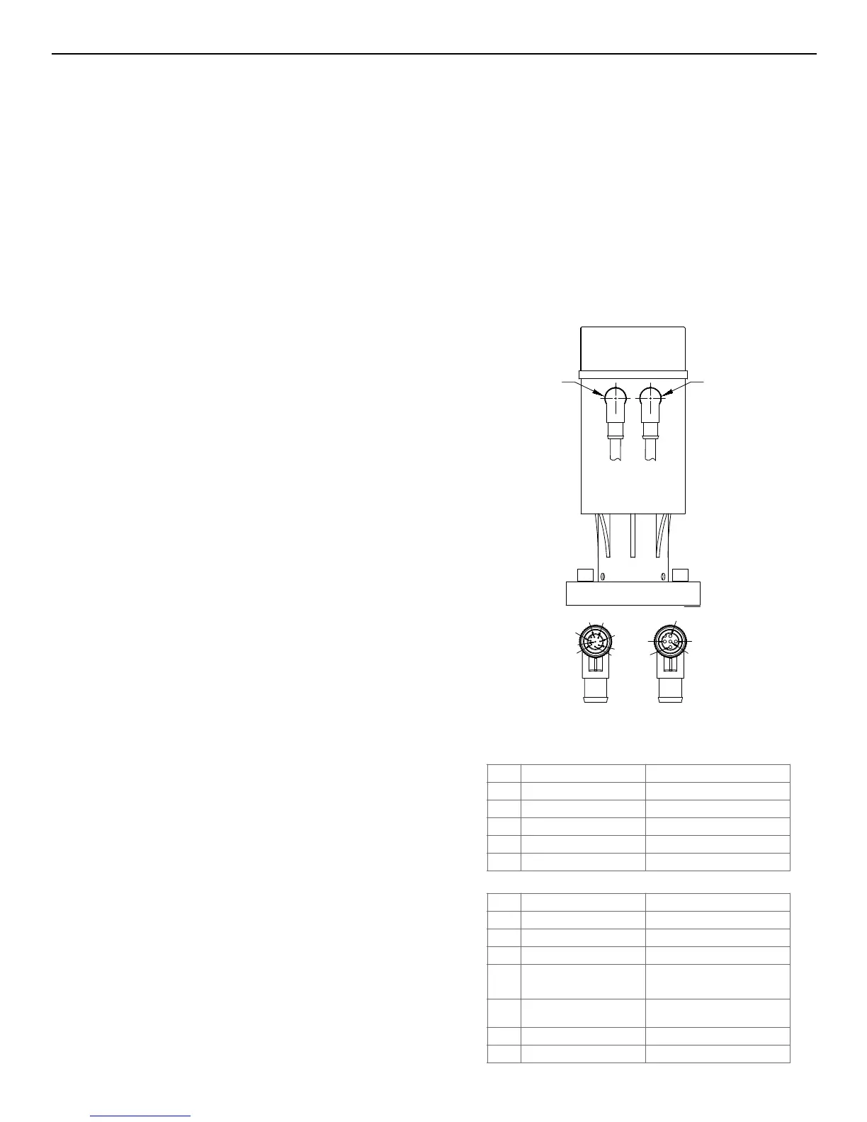
CABLE CONNECTIONS
There are 2 distinct connection points that reside on the
MCV actuator. Both are M12 male connectors. The power
input consists of a 5 pin keyed connector and the control
signal consists of an 8 pin keyed connector.
The MCV comes standard with 6.5ft (2m) long cables with
M12 female heads. The power input cable consists of a
5 pin head and 22AWG wires. The control signal consists
of an 8 pin head and 24AWG wires. The standard cables
come with flying leads. When an SMV to MCV conversion
kit is purchased for a modulating valve, the cable dongle
will come equipped a connection that will plug into to
existing wiring.
8 PIN SIGNAL
5 PIN POWER
5
2
3
1
4
M12 8-PIN
FEMALE
3
4
5
1
2
8
7
6
M12 5-PIN
FEMALE
GREEN
RED
Under Electrical Information & Wiring section on MCV Bulletin Page 15 –
CABLE CONNECTIONS
There are 2 distinct connection points that reside on the MCV powerhead. Both are M12 male connectors. The
power input consists of a 5 pin keyed connector and the control signal consists of an 8 pin keyed connector.
The MCV comes standard with 6.5ft (2m) long cables with M12 female heads. The power input cable consists of a 5
pin head and 22AWG wires. The control signal consists of an 8 pin head and 24AWG wires. The standard cables come
with flying leads. When an SMV to MCV conversion kit is purchased for a modulating valve, the cable dongle will
come equipped a connection that will plug into to existing wiring.
M12 - 8 Pin Connector M12 - 5 Pin
Connector
Power Connector – 5 Pin Red Cable
Signal Connector – 8 Pin Green Cable
Pin # Wire Color Description
1 Brown Not Used
2 White Not Used
3 Blue (+) Backup Power Supply
4 Black (+) 24VDC/24VAC
5 Gray (-) 24VDC/24VAC
Pin # Wire Color Description
1 White Not Used
2 Brown (-) 4-20mA Feedback Signal
3 Green (+) 4-20mA Feedback Signal
4 Yellow (-) Input Signal/Ground
A
dd in (Voltage Modulating, Current Modulating, Slow/Open Close) wiring diagrams after this section.
The Motorized Control Valve can be wired to an optional power backup system that will control the valve to a user
defined location upon a loss of the incoming voltage. These locations of fully open, fully closed, or another open
position can all be programmed through the user interface display. The Uninterruptable Power Supply (UPS) consists
of a voltage monitoring system as well as an integrated battery. The optional UPS when combined with an
appropriately sized DC power supply can run up to 3 Motorized Control Valves. If the incoming line voltage drops
below 19 volts and the power backup system is active, the system will switch over to use the battery power. This
UPS mode is indicated by a slow flashing green LED as seen on the diagram below. The RED illuminate when there is
an issue or the battery needs to be replaced. Once the incoming voltage level is restored, the valve will
automatically return to normal control mode.
HUPS LED Mode Indicator – Green LED
HUPS LED Alarm Indicator – Red LED
5 Gray (+) 0/4-20mA Input Signal
6 Pink (+) 0-5/10VDC & Relay Input
Signal
7 Blue Not Used
8 Red Not Used
FIGURE 30
MOTORIZED CONTROL VALVE OPERATION