20
R649c
SEPTEMBER 2018
MANUAL CONTROL TOOL (MCT)
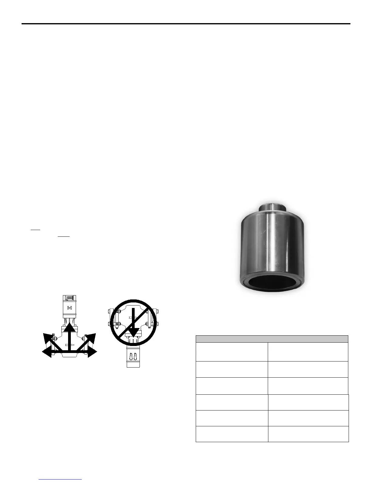
The V-port can be manually actuated by using the Manual
Control Tool (MCT), see Figure 14. To utilize the MCT, the
actuator would need to be removed from the valve. This
can be done by first removing the cables plugged into
the actuator, power (red) cable followed by the signal
(green) cable. The valve v-port will remain in the same
position it was at when cable was unplugged. Remove
the actuator by loosening the three set screws at the
base. DO NOT REMOVE THE BONNET. Place the MCT
over the cartridge and turn the MCT clockwise to open or
counterclockwise to close. Before re-installing rotate the
MCT counterclockwise until the V-port is closed. Refer
to TABLE 25 for the number of turns to fully actuate the
valve. MCT is required to install V-port fully onto cartridge
or remove V-port from cartridge (this includes during
converting from SMV to MCV).
To reinstall the actuator, follow the instructions on page 21.
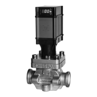
INSTALLATION OVERVIEW
Protect the interior of valve from dirt and moisture during
storage and installation. Valve should be installed so
that the arrow on the valve body is in direction of normal
refrigerant flow. System should be free from dirt, weld slag
and rust particles. A 60 mesh, close-coupled strainer is
available for installation at inlet of valve for 3/4˝, 1˝ and
1-1/4˝. Do not close-couple strainers to 1-1/2˝ through 2˝
Motorized Control Valves.
Please note: Valve will not backflow if in closed position.
Do not install check valves upstream of the Motorized
Control Valve without hydrostatic pressure relief. Do not
close the hand valve on inlet or outlet without making sure
valve is in the open position.
1/4˝ NPT Gauge/Purge port connections are provided on
the inlet and outlet of the 3/4˝ thru 2˝ valves standard.
Pipe sizing, valve placement, rating, anchoring, and similar
prudent precautions should be taken to ensure “liquid
hammer” will not occur when valves open or close.
For proper flange gasket sealing, care must be taken
when threading or welding to assure flanges are parallel
to each other and perpendicular to pipe. Also, gaskets
should be lightly oiled and all bolts should be lubricated
with an anti-seize and must be tightened evenly.
Protect cables during installation.
Do not mount the valve with the motor in the down position.
The valve will only operate properly if the motor is mounted
in a horizontal or upright position. Refer to diagrams
below. Horizontal mounting of motor is satisfactory if oil
and dirt are controlled.
MOTORIZED CONTROL VALVE INSTALLATION
TABLE 25
NUMBER OF TURNS TO ACTUATE VALVE
VALVE PORT SIZE
INCH
(MM)
NUMBER OF TURNS
1/16” THRU 9/32”
(2 THRU 7)
6
3/4” THRU 1-1/4”
(20 THRU 32)
7
1-1/2” THRU 2”
(40 THRU 50)
12
3”
(80)
18
4”
(100)
20
FIGURE 14