Do you have a question about the HANYOUNG NUX LC Series and is the answer not in the manual?
| Hopper Capacity | 500 notes |
|---|---|
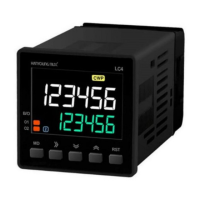
| Display | LCD |
| Batching | Yes |
| Add Function | Yes |
| Counterfeit Detection | UV, MG, IR |
| Power Supply | AC 50/60Hz |
| Functions | Counting, Batching, Adding |
Indicates an imminently hazardous situation which, if not avoided, will result in death or serious injury.
Indicates a potentially hazardous situation which, if not avoided, could result in death or serious injury.
Indicates a potentially hazardous situation which, if not avoided, may result in minor injury or property damage.
Details on power voltage, consumption, and related settings for the LC series devices.
Covers counting speed, power outage compensation, input signal types, and minimum signal time.
Information on output types (SPDT, SPST, NPN), capacity, and timing configurations.
Details on Modbus RTU protocol, RS485 method, speed, distance, and connections.
Includes insulation resistance, dielectric strength, noise immunity, shock, and vibration durability.
Setting the device operation mode for counter or timer functions via button presses.
Configuration for input methods (voltage/non-voltage) and signal types for counting.
Defines the behavior of control outputs (1-stage, 2-stage) and their associated settings.
Options to lock or unlock keys to prevent unauthorized changes to settings.
Configure input logic by selecting voltage or non-voltage based on the NPN/PNP display.
Details on connecting sensors for non-voltage (NPN) and voltage (PNP) input types.
Guidelines for connecting contactless and contact outputs, including load considerations.
Describes the different key lock levels available for user interface protection.
Procedure to change SET1/SET2 values for 2-stage output models using MD and arrow keys.
Instructions for modifying batch counter set values and batch set values via the interface.
Defines available time ranges for timer settings in UP and DOWN modes, with notation.
Steps to view and modify timer set values (SET1/SET2) for 2-stage models.
Description of batch timer operation, including batch count and output logic.
Structure of a query command sent from the master device to the counter.
Structure of a response message from the counter to the master device.
Details and example for reading coil status using Function Code 01H.
Details and example for reading input status using Function Code 02H.
Details for reading holding registers using Function Code 03H.
Details for reading input registers using Function Code 04H.
Details for forcing a single coil status using Function Code 05H.
Describes exception codes and their meanings for communication errors.
Maps output status and reset functions to specific addresses and functions.
Maps input status parameters to specific addresses and functions.
Maps SV, counter, timer, and communication settings to addresses and functions.
Maps product information and monitoring parameters to addresses and functions.
Sets the timer operation mode: Counter, Timer, Twin Timer, Batch Counter, Batch Timer.
Defines the time range settings (seconds, minutes, hours, days) for timer operations.
Configures the scale for timer settings, either Decimal or Sexagesimal.
Specifies the timer output behavior (e.g., ON delay, OFF delay, Interval, Flicker).
Sets the communication address for the device.
Configures the communication baud rate (bits per second).
Sets the data parity for error checking (None, Odd, Even).
Specifies the number of stop bits used in communication.
Sets the time the device waits for a response to a communication command.
Enables or disables writing data to the device via communication.
Physical dimensions and panel cutout specifications for the LC3 model.
Physical dimensions and panel cutout specifications for the LC4 model.
Physical dimensions and panel cutout specifications for the LC6 model.
Physical dimensions and panel cutout specifications for the LC7 model.
Wiring diagrams for LC3 models: 1-stage, No sub, 2-stage, and RS485 outputs.
Wiring diagrams for LC4 models: 1-stage, No sub, 2-stage, and RS485 outputs.
Wiring diagrams for LC6 models: 1-stage, No sub, 2-stage, and RS485 outputs.
Wiring diagrams for LC7 models: 1-stage, No sub, 2-stage, and RS485 outputs.