Page 6 For technical questions, please call 1-888-866-5797. Item 62292
SAFETY OPERATION MAINTENANCESETUP
Specifications
Electrical Rating
120VAC / 60Hz / 9A
@ 40A, 12V Setting
Charge Settings
2A, 12V
10A, 12V
40A, 12V
Starter Settings
100A, 6V
60 second maximum with 90 second minimum rest
200A, 12V
5 second maximum with 240 second minimum rest
Battery Cables
6' 6"
Red = Positive
Black = Negative
Power Cord 6' 5"
Timer Settings 0-180 minutes (up to 3 hours), and continuous (HOLD)
Assembly Instructions
Read the ENTIRE IMPORTANT SAFETY INFORMATION section at the beginning of this
manual including all text under subheadings therein before set up or use of this product.
TO PREVENT SERIOUS INJURY: Unplug the charger, disconnect any battery,
and allow charger to cool completely before assembling or making any adjustments to the charger.
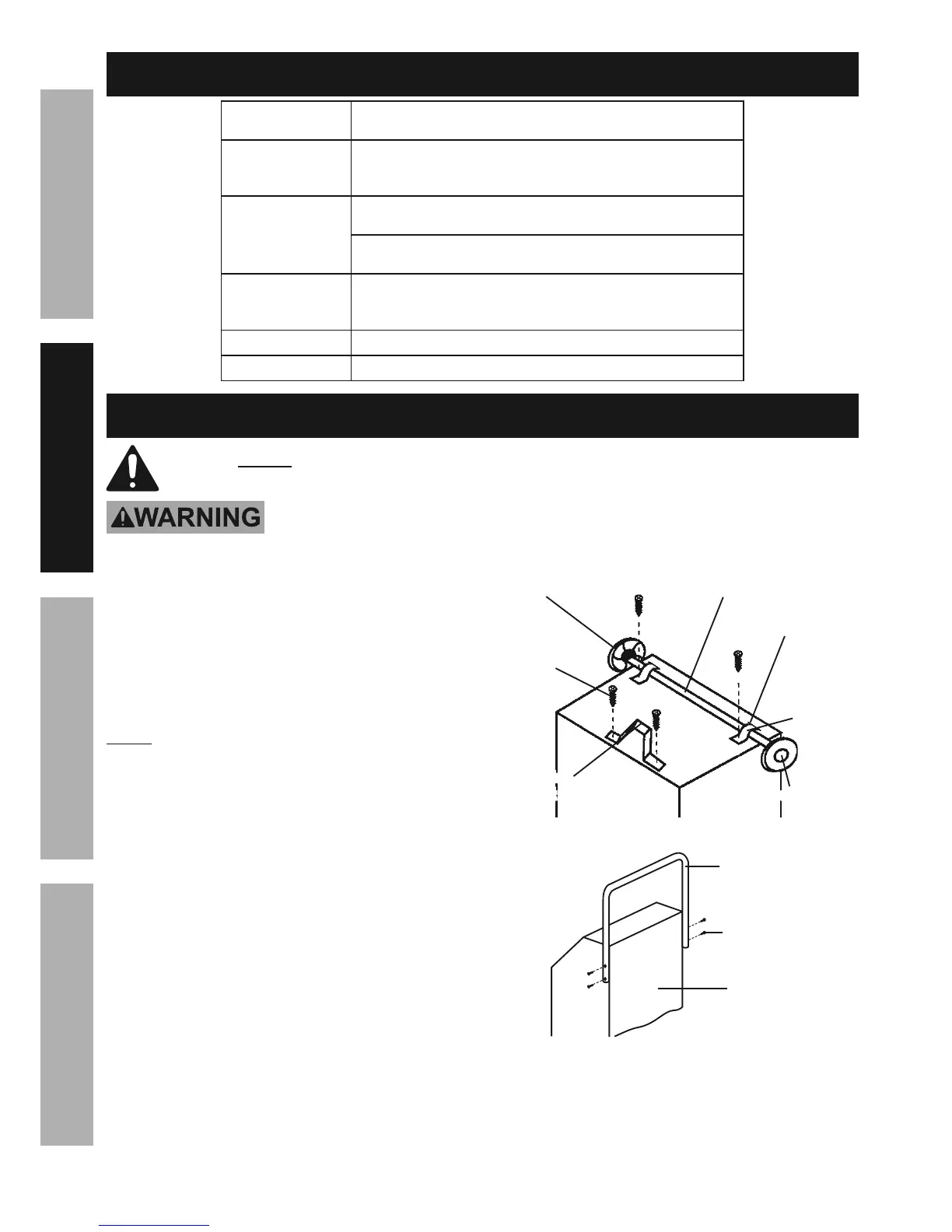
1. Place the Battery Charger/Starter on its side.
2. Use two Screws to install the Mounting Foot to the
front bottom of the Charger/Starter. See Figure A.
3. Slide the Wheels onto the ends of the Axle and
slide an Axle Cap onto each wheel. If needed,
tap on the Axle Caps with a rubber mallet.
NOTE: Verify the Hub of each Wheel is facing in.
4. Set the Axle along the bottom of the Charger/Starter
and Align the Axle Brackets with the mounting
holes. Once aligned, fasten the Wheel Axle into
place by sliding the bracket tabs into the slots,
and securing with two screws. See Figure A.
5. Stand up the Charger/Starter.
6. Remove the two top screws on each side of the
Charger/Starter and set the Handle against the
unit, aligning the mounting holes. See Figure B.
7. Use the Screws to mount the Handle on the
sides of the Charger/Starter. See Figure B.
Figure A: Foot and Wheel Installation
Axle
Mounting
Foot
Wheel
Axle Cap
Axle
Bracket
Screws
Figure B: Handle Installation
Handle
Screw
Charger/
Starter
Slot