8
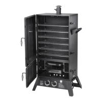
STEP 3
Locate: Control Panel Assembly [4] and Burner
Chamber Assy.[3], two 1/4-20x1/2” Screw [1a] (two
remaining from previous step).
Tools needed: Philips head screwdriver.
Procedure:
• Place the control panel assembly between the
front legs as shown. There are slots on the
control panel that t around the legs and line up
with the bolt holes.
• Be sure all the tabs on the back side of the
control panel are captured around the legs as
shown below.
• Insert the two remaining screws and tighten
them securely.
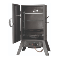
STEP 4
Locate: Burner Chamber Assembly [3], three
1/4-20x1/2” Screw [1a] from Hardware Pack - Blister
card.
Tools needed: Philips head screwdriver.
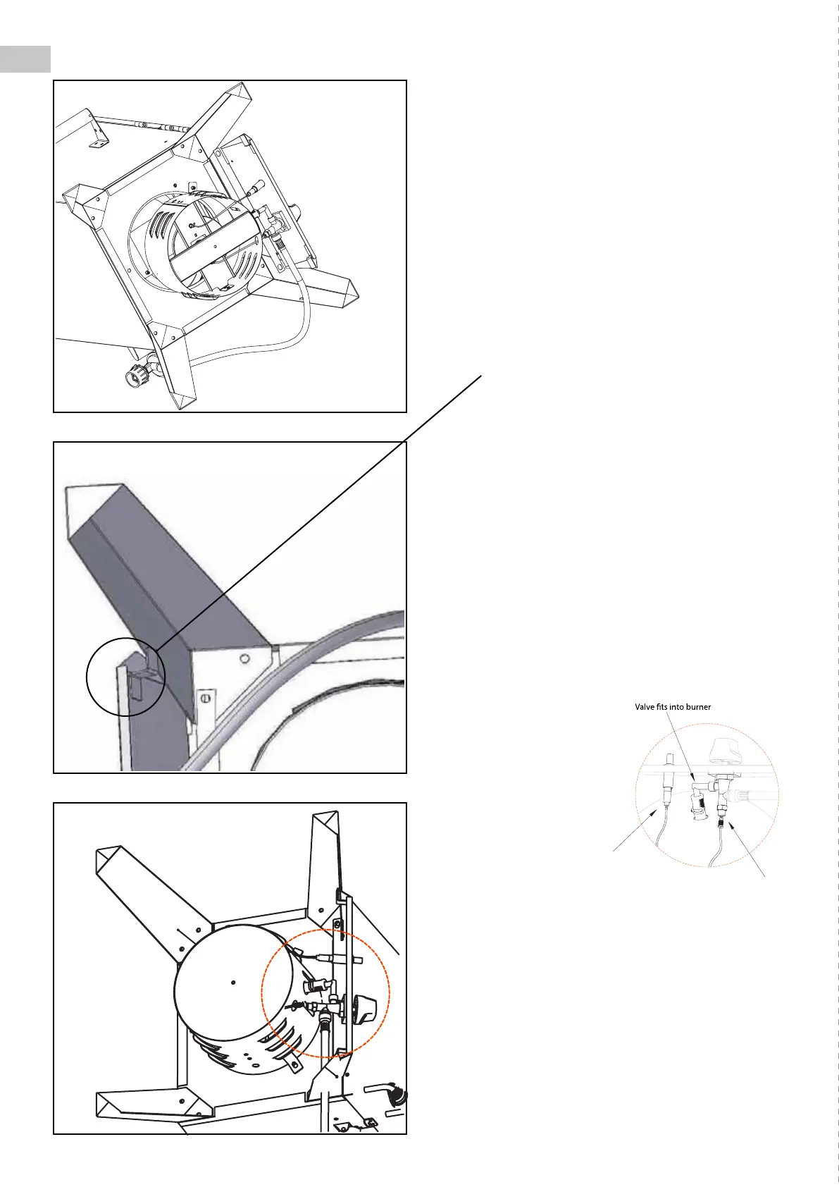
Note: Inspect the burner chamber prior to assembly
to make certain the burner tube is correctly over the
end of the valve as shown:
Procedure:
• Align the burner
chamber assembly
[3] underneath
the smoker as
shown. Do not
remove Control
Knob or loosen
the attaching
screws to align the
burning chamber
tube to the valve.
• Place the body of the burner chamber assembly
so that it sits ush with the bottom of the
cabinet. The mounting holes and mounting tabs
should line up.
• For each mounting hole, insert a 1/4-20x1/2”
screw [1a]. Secure the burner assembly with the
three screws from the inside of the cabinet.
• Securely tighten all three screws.
(Factory tted)
(Factory tted)
Ignition wire
Thermocouple wire
connecting thread
 Loading...