TM
9-879
51
MOTORCYCLE, SOLO
[HARLEY-DAVIDSON MODEL WLA]
(4)
Engage remaining
steel disk
with shell spHnes
with "OUT"
side
facing
outward.
(5)
Install
"siDrung" (one side lined)
steel
disk, lined side inward,
on
clutch hub studs.
(6)
It
will
be
noted that the three long, threaded-end, clutch hub
studs
are not spaced an equal distance apart. It will also
be
noted
that the three holes (keyhole shaped) in the spring collar
are
not
spaced equidistantly. Therefore,
when installing
releasing
disk
and
spring assembly on clutch hub studs, the three threaded
studs
and
holes
in
spring collar must be alined. Install assembly
on studs, re-
place the three
nut locks,
replace the three adjusting
nuts, and
tighten all three
evenly
until the distance between shoulder
of
spring
collar and face
of releasing
disk is
IV32
i^ich (fig.
27).
(7)
Remove the large washer and replace push
rod adjusting
screw lock nut.
Do
not attempt adjustment of clutch
release lever
and push rod adjusting screw until outer front chain
guard and foot-
board
have
been
installed.
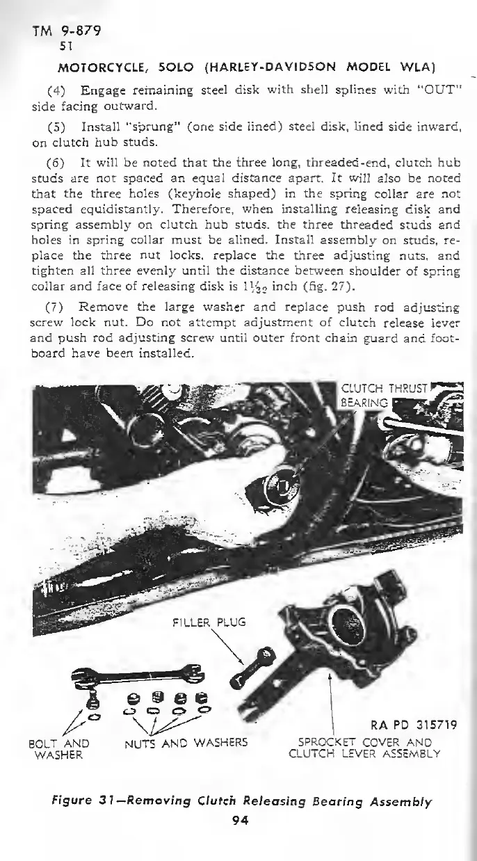
BOLT
AND
WASHER
NUTS
AND
WASHERS
RA
PD
315719
SPROCKET
COVER AND
CLUTCH LEVER ASSEMBLY
Figure
31 —Removing
Clutch Releasing
Bearing
Assembly
94



 To Next Page