EasyManua.ls Logo

Harlock-RC VIPER 140 - User Manual

Harlock-RC VIPER 140
22 pages
Print Icon
To Next Page IconTo Next Page
Loading...
VIPER 140 Manual
Release 1.0 January 2018
Please read this user manual carefully, it contains instructions for the correct assembly of the model.
Please refer to the web site www.harlock-rc.com for updates and other important information.
Thank you for your purchase, we hope you enjoy your new Airplane.
For sales and info inquiries please e-mail sales@harlock-rc.com
Specifications:
Wing span: 1400mm
Length: 1250mm
Radio: Minimum 8 channel | 8 micro servos
EDF: 90mm | 5000-5500mah 6s
Weight: 4,200Kg (with battery)
Inside the box:
Complete structure
Linkages
Screws and bolts
Thrust tube (electric version)
Carbon round tubes for wings and stabs
Hinges, Horns and servo holders already mounted
Additional required:
8 micro servo
EDF 90mm
Landing gear
LiPo battery pack 5000-5500mah 6s
NOTES FOR ASSEMBLY
Please refer to this manual for assembly instructions for this model.
Each step is based on the work done in the previous step. Changing the order of assembly may result in
additional or unnecessary steps.
1
Question and Answer IconNeed help?

Do you have a question about the Harlock-RC VIPER 140 and is the answer not in the manual?

Summary

Aircraft Specifications and Contents

Specifications

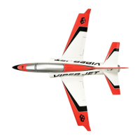
Details model dimensions, radio, EDF, and weight.

Package Contents

Lists all items included in the box.

Required Additional Items

Lists components not included but necessary for operation.

Assembly Guidance

Provides general notes and best practices for assembly.

Control Surface Servos Installation

Aileron Servo Mounting

Instructions for installing servos on the wings for ailerons.

Flap Servo Mounting

Instructions for installing servos on the wings for flaps.

Rudder Servo Mounting

Instructions for installing the servo for the rudder.

Elevator Servo Mounting

Instructions for installing servos for the elevators.

Landing Gear Installation

Wing Landing Gear Attachment

Details the process of attaching landing gears to the wings.

Nose Landing Gear Attachment

Details the process of attaching the nose landing gear.

Fuselage and Propulsion System Assembly

Elevators to Fuselage Attachment

Describes securing elevators to the main aircraft body.

ESC Installation and Securing

Guide for installing the ESC and securing it.

Thrust Tube and Fan Assembly

Instructions for fitting the thrust tube and fan unit.

Fan Cover Installation

Details how to attach the fan cover.

Final Assembly and Electronics Connection

Main Wings Attachment

Covers the process of attaching the main wings to the fuselage.

Receiver and Battery Setup

Connects the receiver, landing gear control, and battery.

Flight Control Configuration

Maximum Surface Travel Settings

Configures control surface throws for takeoff/landing.

Dual Rate Settings for Flight

Sets control surface throws for in-flight adjustments.

Flight Preparation and Safety

Center of Gravity (CG) Calculation

Specifies the correct CG point for balanced flight.

General Safety Guidelines

Provides crucial safety rules for operation.

Important Disclaimers and Notes

Important Operational Notes

Contains vital warnings and information for users.

Harlock-RC VIPER 140 Specifications

General IconGeneral
Power SourceElectric
Max Speed20 km/h
Chassis MaterialPlastic
SuspensionIndependent
Motor TypeBrushed
Battery TypeLi-ion
Battery Capacity800mAh
Scale1/14
Tire TypeRubber
Charging Time120 minutes
Run Time15 minutes