EasyManua.ls Logo

Harmonic ProView PVR-8140 - User Manual

Harmonic ProView PVR-8140
2 pages
Print Icon
To Next Page IconTo Next Page
Loading...
Contacting Harmonic:
wm-cband-help@harmonicinc.com
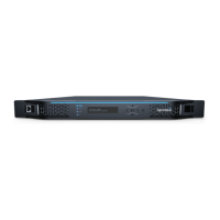
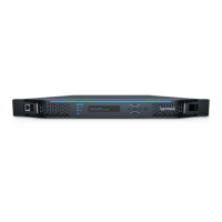
ProView PVR-8140 Decoder — Quick Start Guide
3. Configuring the Decoder Input & Output
The PVR 8140 can be configured via the front panel (the menu tree is in Section 6)
or remotely through the management IP port and embedded GUI.
The PVR 8140 decoder has two modes:
 Multiplex - In Multiplex mode the device generates a new stream and user can
select which programs to pass and also able to modify the bitrate.
 Transparent - In transparent mode, the whole output stream is passed to the
output unchanged.
The steps for configuring the PVR 8140 via the front panel are:
1. Navigate to Root > Input > Primary Port Selection.
2. Select ASI as the input port.
3. Navigate to Root > Decoding> Configuration > Program Selection > Service
Mode.
a. Select Program to output.
A list of all input programs received displays.
b. The screen displays the program number (decimal., program
name if the input stream provides an SDT table and the status (CAS/
scrambled or FTA/free to air).
c. Select a program.
d. Verify output video and audio on your monitoring device
If you would like of control the PVR8140 via the IP management interface, please
set up the IP address as described in Section 5 of this guide.
5. OPTIONAL - Setting up Management IP
Address
In order to use the Management IP interface, you will need to first
configure the management IP parameters via the front panel:
1. Press ENTER on the keypad.
The root menu appears.
2. Navigate to Unit > Management Port > IP Configuration
3. Set the IP Address, Subnet Mask, and Default Gateway for the
management port. Make sure that DHCP is set to Disable.
For further details on the management IP interface and its usage, please
refer to user manual on using the embedded GUI.
2. Cable Connections
Once you have installed and configured the XOS IRD, and assigned the desired
program(s. to one or more ASI output ports, you are ready to proceed with
connecting and configuring the PVR 8140
Please refer to the PVR 8140 backplane and sample wiring diagrams on
Page 2 of this guide.
Note: Eight (8) Mini-BNC to BNC adapter cables are provided with each XOS IRD.
1. Connect the ASI cable from the XOS IRD ASI port to the PVR 8140 ASI input..
If you have more than 8 analog channels, cascading the ASI as illustrated in the
Sample Wiring Diagram (Section 8 of this guide).
2. Connect the composite video and audio cables to your analog modulator or
analog Ad Insertion system. You can initially connect to a monitor to verify
composite output.
1. Rack Mounting

It is recommended the PVR 8140 be installed and secured in a standard EIA
19" rack

Electrical connection: The ProView 8140 is powered by an AC power supply.

The PVR 8140 is intended for a maximum operating ambient temperature of
50° C. Please ensure there is enough room for a column of cold air to
circulate on the front of the chassis and a column of hot air to circulate on
the rear of the chassis, from bottom to the top of the rack
6. PVR 8140 Front Panel Menu Heirarchy
If you have an analog ad insertion system and need to set up DTMF tones
on the PVR, Wire the PVR 2
nd
Audio left output +/- to the DTMF input on the
ad insertion system. Please follow these steps via the front panel to
configure the correct DTMF for each channel (note DTMF may be unique for
each channel..
1. Select Decoding.
2. Select Configuration.
3. Select DPI.
4. Select Trigger (SCTE 35., and set the following parameters:
 OON Trigger > GPI3 & DTMF2. Trigger (SCTE 35. >
 OON DTMF> Enter up to four DTMF tones (0-9, *)
 DTMF Mode - enable
 OON DTMF [024*] -
TONE1 - 0
TONE2 - 2
TONE3 - 4
TONE4 - *
 RTN Trigger > GPI3 & DTMF2. Trigger (SCTE 35. >
 RTN DTMF> Enter up to four DTMF tones (0-9, #)
 RTN DTMF [024#] -
TONE1 - 0
TONE2 - 2
TONE3 - 4
TONE4 - #
5. Verify that the Ad Insertion is working.
6. Adjust pre-roll on the PVR for timing adjustments as necessary.
4. OPTIONAL - Setting up DTMF (Cue Tones.
for Analog Ad Insertion
https://www.harmonicinc.com/documentation/warner-media/
Question and Answer IconNeed help?

Do you have a question about the Harmonic ProView PVR-8140 and is the answer not in the manual?

Overview

The Harmonic ProView PVR-8140 Decoder is a professional device designed for decoding and processing video and audio signals, primarily for analog ad insertion and distribution. It supports various input and output formats, offering flexibility in different broadcast environments.

Function Description:

The PVR-8140 serves as a decoder that takes ASI (Asynchronous Serial Interface) inputs, typically from an XOS IRD (Integrated Receiver/Decoder), and outputs composite video and analog audio. It can operate in two primary modes:

  • Multiplex Mode: In this mode, the device generates a new stream, allowing users to select specific programs to pass through and modify their bitrate.
  • Transparent Mode: The entire output stream is passed through unchanged.

A key feature of the PVR-8140 is its support for DTMF (Dual-Tone Multi-Frequency) cue tones, which are essential for analog ad insertion systems. This allows for precise triggering of advertisements based on SCTE 35 standards. The device can be configured to recognize specific DTMF tone sequences for both "OON" (On-Net) and "RTN" (Return) triggers, enabling seamless integration with ad insertion workflows.

The decoder also supports input redundancy, allowing for a primary and backup input port (ASI-1 and ASI-2) to ensure continuous operation in case of a signal loss. It includes features for de-jittering, alarm thresholds, and program forwarding.

Important Technical Specifications:

  • Input Ports: Primarily ASI (Asynchronous Serial Interface). It can receive signals from DVB-S/S2/S2X ports (1, 2, 3, 4) and Internet DPR sockets (1, 2).
  • Output Ports: Composite Video Out, Analog Audio Out (ANLG. AUD 1, ANLG. AUD 2). It also supports AES/EBU digital audio and HD-SDI.
  • DTMF Support: Configurable for SCTE 35 triggers, with the ability to define up to four DTMF tones (0-9, *) for OON and (0-9, #) for RTN.
  • Rack Mounting: Standard EIA 19" rack mountable.
  • Power: AC power supply (100-240VAC 1A 50/60 Hz).
  • Operating Temperature: Maximum ambient temperature of 50° C. Proper airflow is required for cooling.
  • Management Interface: Front panel menu, embedded GUI accessible via a management IP port (GbE).
  • Redundancy: Input redundancy scheme with configurable triggers.
  • Decoding Features: Program selection, video, audio, POR (Program Output Rate), VBI/WANC, OSD (On-Screen Display), TS settings, program forwarding, descrambling, PDS (Program Data Service), MPE (Multi-Protocol Encapsulation), DPI (Digital Program Insertion).

Usage Features:

  • Front Panel Control: The device can be fully configured via its front panel menu, providing access to input, decoding, output, port settings, active alarms, presets, and unit information.
  • Remote Management: A comprehensive embedded GUI is available via the management IP port (GbE), offering an alternative and often more convenient method for configuration and monitoring. This requires setting up the IP address, subnet mask, and default gateway.
  • Cable Connections: Utilizes Mini-BNC to BNC adapter cables for ASI connections. Supports cascading ASI inputs for systems requiring more than 8 analog channels.
  • Ad Insertion Integration: Designed to integrate with analog ad insertion systems by providing DTMF cue tones. The pre-roll can be adjusted for timing.
  • Program Selection: Users can select specific programs from the input stream to output, viewing details such as program number, name, and CAS/scrambled/FTA status.
  • Monitoring: Initial setup allows connecting to a monitor to verify composite video and audio output.
  • Redundancy Configuration: Allows setting up primary and backup input ports and defining redundancy triggers for robust operation.

Maintenance Features:

  • Alarms and Thresholds: The device provides alarm thresholds for monitoring various parameters, helping to identify and troubleshoot issues proactively.
  • DMS (Device Management System) Info: The front panel menu includes a "DMS Info" section, which likely provides diagnostic information, authorized programs, and blacked-out programs, aiding in system maintenance and troubleshooting.
  • Physical Installation: Requires proper rack mounting and ensuring adequate airflow (cold air from front to back, hot air from bottom to top) to maintain the operating temperature and prevent overheating.
  • Documentation: A user manual is available for detailed instructions on using the embedded GUI and other advanced features.

Harmonic ProView PVR-8140 Specifications

General IconGeneral
BrandHarmonic
ModelProView PVR-8140
CategoryMedia Converter
LanguageEnglish

Related product manuals