HARRIS PRODUCTS GROUP 920 SERIES
GAS DISTRIBUTION EQUIPMENT Installation and Operation Manual SWITCHOVER SYSTEM
THIS BOOKLET CONTAINS PROPRIETARY INFORMATION FROM THE HARRIS PRODUCTS GROUP. IT IS PROVIDED TO THE PURCHASER SOLELY FOR
USE IN CONJUNCTION WITH AUTOMATIC SWITCHOVER MANIFOLDS MODEL 920 SERIES.
General Precautions –
• Installation should be performed by personnel knowledgeable in the handling of compressed gases.
• Choose a location well ventilated for installation
• Use proper precautions when dealing with any compressed gas.
• The user should be familiar with the chemical and reactive properties of the gas being used (Read the MSDS of the gas being used).
Reference Material –
The following safety bulletins are available from the Compressed Gas Association (www.cganet.com)
• SB-2 Oxygen Deficient Atmospheres
• SB-10 Correct Labeling & Proper Fittings On Cylinders/Containers
• SB-15 Avoiding Hazards In Confined Work Spaces During Maintenance, Construction And Similar Activities
• SB-19 Potential Valve Thread & Cylinder Thread Mismatch
General Instructions -
Switchover Manifolds should be installed in accordance with guidelines stated by the National Fire Protection Association, the Compressed Gas
Association, OSHA and all applicable local codes. Switchover manifolds should not be placed in a location where the temperature will exceed
120°F (49°C) or fall below –20°F (-29°C) for sustained periods of time. A manifold placed outside in an open location should be protected against
rain and excessive moisture. During winter, protect the manifold from ice and snow. The manifold should be located in a clean, well-ventilated
area which is free of oil and combustible materials.
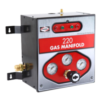
Introduction
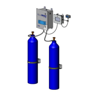
The changeover panel is designed to provide continuous uninterrupted gas flow for applications using cylinder gas supplies up to 3000 PSIG. Ideal
for high purity applications, this panel consists of two high purity primary and line regulators, gauges, isolation valves, and mounting panel.
Unscheduled downtime created by depleted cylinders can be eliminated with this panel incorporated into your system. When the primary side is
consumed, the panel automatically switches to the reserve supply and feeds the process at a constant pressure. The line regulator eliminates
virtually any pressure variation associated with this switch.
Maximum Inlet Pressure: 3000 PSIG
Outlet Pressure: 10 - 100 PSIG or 20-200 PSIG (User Adjustable)
Maximum Flow Rate: 200 SCFH