Do you have a question about the Harris RF-3200 Series and is the answer not in the manual?
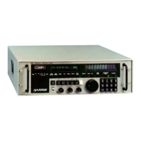
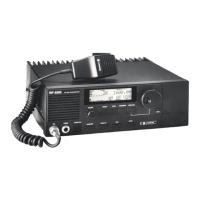
Overview of the service manual's purpose and content.
Lists of parts and ancillary kits for the RF-3200 transceiver.
Step-by-step guide for entering and modifying configuration settings.
Categorization and explanation of programmable configuration parameters.
Detailed explanations for each configurable parameter.
Procedures for removing and accessing various radio assemblies.
Lists of parts and diagrams for assembly interconnections.
Essential precautions for handling static-sensitive electronic components.
Charts and guides for diagnosing and resolving common faults.
Procedures for calibrating and adjusting various PWB assemblies.
Lists necessary test equipment for maintenance and adjustments.
Description of how signals flow through the receiver section.
Description of how signals flow through the exciter section.
Lists of components and diagrams for the heatsink assembly.
Details on the digital control circuit of the logic PWB.
Details on the audio processing circuit of the logic PWB.
Details on the automatic level control circuit of the logic PWB.
Explanation of the synthesizer PWB assembly's functions and frequency calculations.
Description of the Local Oscillator 1 circuit.
Description of the Local Oscillator 2 circuit.
Description of the Local Oscillator 3 circuit.
Lists of components and diagrams for the synthesizer PWB assembly.
| Frequency Range | 1.6 MHz to 30 MHz |
|---|---|
| Modes | USB, LSB, AM, CW |
| Sensitivity | 0.5 μV for 10 dB S/N (SSB, CW) |
| Selectivity | 6 kHz (AM) |
| Power Supply | 115/230 VAC, 50-400 Hz; 24 VDC |