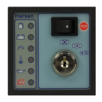
GU301A Controller Operation Manual Harsen™
- 2 -
3. Back Panel
The descriptions of 11 connecting terminals on back panel:
NO. Code Description Mode Polarity
1
(
)
battery cathode input cathode
2
(
)
battery anode input anode
3 AR start output anode
4 SV outlet overspeed input cathode
5 FL fuel level input cathode
6 ATA high coolant temp input cathode
7 BPA low oil pressure input cathode
8 PD Fuel output anode
9 PE stop output anode
10 AL alarm output anode
11 D+ excitation input/ output anode
4. Performance
The general information of the internal logical of GU301A controller as following:
1) When control start, rotating key clockwise, an auto Lamp test period, alarm and an internal diagnose
begins, LED indicator keeps on. If the protect functions of ATA and BPA are enabled, the LED will turn
on, but alarm will not sound, turn key right will start engine, protect control stay at monitoring mode.
2) Engine start period is 10s, during the period, the alarm of ATA and BPA are not enabled, but the
protection of overspeed is enabled and the alternator of battery charger is excited by the D+ terminal
of connector, the protect functions of ATA and BPA are enabled after 10s, excitation period is finished.
3) If one of protect functions of BPA, ATA and or overspeed is enabled, its LED will turn on and send out
alarm, and then begins stop period for 30s.
4) If GU301A controller already connected to power source, but engine still can not successfully start
after 30s, control will enter into monitoring mode to find out possible failure.
5. Technical Characteristics
Description Min. Tip. Max. Unit
the dimension of control panel 72×72 mm
high 82.5 mm
source voltage 8 35 Vdc
the adjust range of overspeed 50 70 HZ
the range of operating temperature -20 +50 ℃
(
)
30mA/30Vdc mA
the input range of external overspeed 0 2 Vdc
the input range of fuel level 0 2 Vdc
the input range of high temperature 0 2 Vdc
the input range of low oil pressure 0 2 Vdc
(
)
16A/30Vdc A
(
)
16A/30Vdc A
(
)
300mA/30Vdc mA
(
)
600mA/30Vdc mA
Items Period Begin from connect
Begin from start
stop period 30 S
D+ excitation period 10 S
overspeed delay 30 S 1 S
fuel level storage delay 1 S
ATA delay (high coolant temp) 40 S 10 S
BPA delay ( low oil pressure) 40 S 10 S
D+ delay 40 S 10 S

 Loading...