HARTING Electronics GmbH
P.O. Box 14 73 | D-32339 Espelkamp
HARTING.electronics@HARTING.com
Deutsch
E
Français
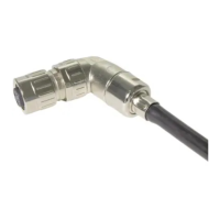
Rundsteckverbinder · C C · Connecteur circulaire
M12 male/female A-coded 5-pole
M12 male D-coded 4-pole
Bestell-Nummer · P · Réf. article
21 03 812 1511 + 21 03 812 2511 + 21 03 882 1411
www.HARTING.com
Inhalt · C · Contenu
Bestell-Nummer
P N
Réf. article
21 03 812 1511 21 03 812 2511 21 03 882 1411
Kontaktträger
C
Support de contact
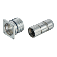
Steckverbinder-
gehäuse
M
Corps métallique
Wellenschlauch-
dichtung
S
Joint d’étanchéité
Adapter
A
Adaptateur
Dichtungskamm
S
Peigne de joints
Schirmring
S
Tresse de blindage
Montagehilfe
A
Dispositif de
montage
Oval-Sperre
O
Clip ovale
Montageanleitung
A · Instructions d’assemblage
1. Wellenschlauch im Wellental gerade abschneiden.
1. C .
1. Couper la gaine annelé droite dans le creux de l’onde.
Hersteller
M
Fabricant
Bezeichnung
D
Désignation
Beschreibung
D
Description
PMA PCST-10B.50
Wellenschlauch
C
Gaine
2. Wellenschlauchdichtung ganz auf den Wellenschlauch aufschieben.
2. P .
2. Pousser le joint d’étanchéité complètement sur la gaine.
3. Benötigte Dichtung ausbrechen.
3. C .
3. Choisir le joint approprié.
4. Wellenschlauch mit der Wellenschlauchdichtung auf das Kabel schie-
ben. Adapter und Dichtung auf das Kabel schieben.
4. P . P
.
4. Pousser la gaine avec le joint d`étanchéité sur le câble. Pousser l‘adap-
tateur et le joint sur le câble.
5. Kabelmantel entfernen. Schirmgeflecht umlegen. Evtl. Folien entfer-
nen. Anschließend Kabelenden abisolieren und Kontakte ancrimpen.
5.
R . F . R
. F .
5. Retirer le gainage. Rabattre la tresse de blindage. Enlever éventuelle-
ment le film de protection si nécessaire. Finalement dénuder les bouts
de câble et sertir les contacts.
4
X
Bestell-Nummer
P N
Réf. article
21 03 812 1511 21 03 812 2511 21 03 882 1411
Abisolierlänge X
S X
Longueur de dénudage X
21 – 23 mm 19 – 21 mm 21 – 23 mm
6. Dichtung über Kabelmantel schieben, bis die Dichtung bündig mit der
Mantelisolation abschließt. Schirmgeflecht zur Dichtung umlegen.
6. S .
S .
6. Glisser le joint sur le câble jusqu’à ce que le joint soit aligné avec l’iso-
lant. Rabattre la tresse de blindage vers le joint.
7. Schirmring über Kabelenden auf Schirmgeflecht und Dichtung aufdrü-
cken. Dabei darauf achten, dass auf den Kodiernasen der Dichtung
kein Schirmgeflecht liegt. Überstehendes Schirmgeflecht abschnei-
den. Bei 4-poligem Anschluss weiter bei Punkt 9. Bei 5-poligem An-
schluss weiter bei Punkt 8.
7. S
. M
. C . I
. I
.
7. Glisser la bague de blindage sur les câbles et assembler le joint et la
bague. S’assurer qu’aucun pion de détrompage n’est couvert par la
tresse. Couper la tresse de blindage.
Pour une connexion 4 pôles, passer au point 9.
Pour une connexion 5 pôles, passer au point 8.
8. Mittleren Kontakt in den Kontaktträger einlegen. Kontaktträger zu-
sammendrücken und verrasten.
8. I .
P .
8. Insérer le contact dans la cavité centrale du support de contact. Assem-
bler le support de contact.
7.2 - 8.8 mm
5.4 - 7.2 mm
4.5 - 5.4 mm